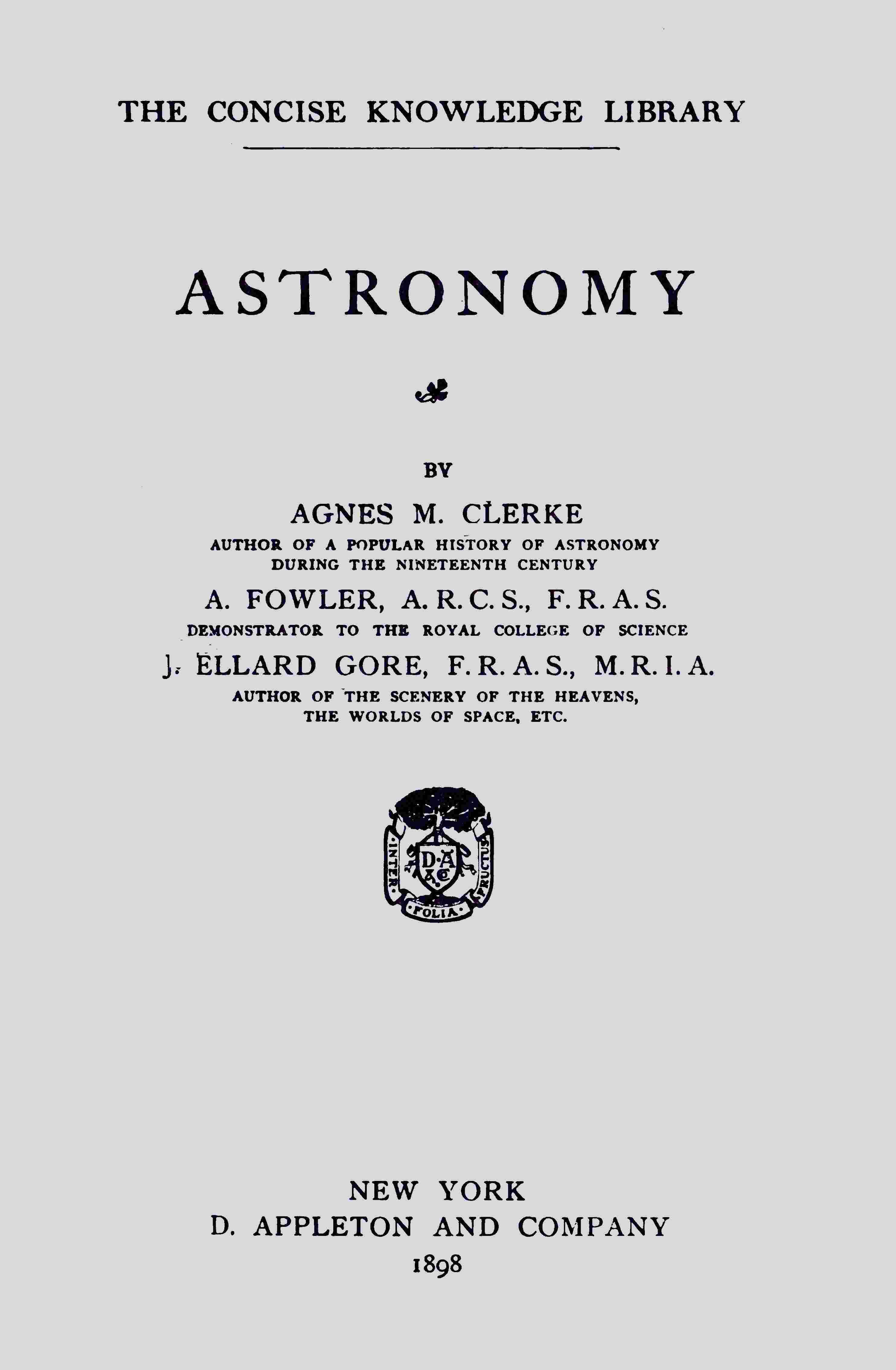
Fig. 52.—The Photographic Telescope employed by Dr. Isaac Roberts.
The new “photo telescopic” object-glass now manufactured by Messrs. Cooke appears to be full of promise. In this lens all the colours of the spectrum are brought to almost exactly the same focal point, so that it serves equally well for photographic or visual purposes.
This difficulty in regard to achromatism does not exist in the case of the reflecting telescope, since rays of light of every colour are reflected at precisely the same angles. For this reason reflectors, when properly managed, give the best photographic results. Dr. Isaac Roberts and Dr. Common are especially identified with the application of the reflecting telescope for celestial photography. The instrument employed by the former consists of a 20-inch reflector, and a 7-inch guiding telescope of the refracting form. The two telescopes are mounted on the extreme ends of the declination axis of an equatorial, a photograph of which we owe to the kindness of Dr. Roberts.
Dr. Common does not employ a guiding telescope at all. The photographic plate which he places at the focus of the reflector is smaller than the field of view, so that by means of an eye-piece fitted with a cross wire at the side of the dark slide, he is able to watch a star near the edge of the field. Both eye-piece and dark slide are attached to a frame which can be controlled by two screws at right angles to each other. If the guiding star leaves the cross wire through errors in driving, or other causes, the eye-piece and dark slide are bodily moved after it by means of the adjusting screws. This method not only has the advantage of saving the cost of a guiding telescope, but reduces the effects of vibration consequent upon the correction of errors by moving the whole telescope.
For photographing the sun a special instrument called a photoheliograph is usually employed. This differs only from an ordinary photographic telescope in being provided with a secondary magnifier, by which means the focal image formed by the object-glass is amplified before falling upon the photographic plate. On a bright clear day, pictures of the sun 8 inches in diameter can be taken with an exposure of about ¹⁄₅₀₀th of a second, and such a photograph will frequently record more facts as to the state of the solar surface than a whole day’s observation. Lenses or mirrors of very long focus are also occasionally employed in solar photography, and in this way a large image is obtained without the use of a secondary magnifier.
Photographs of the moon and planets may be taken either with or without a secondary magnifier, but in either case the exposures are longer than for the sun.
Finally, it may be added that the sensitive plates and processes used in astronomical photography do not differ from those employed by ordinary photographers.
CHAPTER XVI.
INSTRUMENTS OF PRECISION.
The Meridian Circle.—The accurate registration of the positions of the heavenly bodies is one of the most important functions of an astronomical observatory. When the apparent places of an object at a sufficient number of different times have been duly recorded, it becomes possible to investigate the laws upon which its changes of position depend, and to predict its positions at subsequent times for the benefit of navigators and others to whom such predictions are of practical utility. For this purpose various instruments have been devised, but in all cases where it can be employed, the transit circle, or meridian circle, as it is indifferently called, is generally conceded to give the most trustworthy results.
With this instrument the observations are made when the celestial body under observation is crossing the meridian of the place where the instrument is set up, that is, when it “transits,” or “souths.” At this time the accuracy of the observations is least impaired by the ever-varying effects of atmospheric refraction.
The meridian circle consists of a refracting telescope—seldom exceeding 6 inches in aperture—which is fixed to a hollow axis at right angles to itself, and this axis is supported horizontally in an east and west direction, so that the telescope is only free to move in the plane of the meridian. A large graduated circle—or frequently two such circles—attached perpendicularly to the hollow axis, and read by microscopes fixed to the walls or iron pillars which support the axis, completes the essential parts of the instrument.
As the field of view of the telescope covers a considerable area, it becomes necessary to provide some means of marking the exact point within it which represents the meridional axis of the instrument. This is accomplished by placing at the common focus of the object-glass and the positive eye-piece a system of “cross wires,” consisting of tightly-stretched spider threads, two of which are fixed horizontally and nearly in contact, and five or seven vertically at equal distances apart. What the observer has actually to do is to incline the telescope at such an angle that the star is seen to traverse the space between the two horizontal threads, and then to record the exact times, by means of a chronograph and sidereal clock, at which the star appears to cross each of the equidistant vertical threads. By thus making five or seven observations and taking the average, greater accuracy is attained.
The time observations, as we have already seen, determine the right ascension of the star under observation, while the declination is indicated by the readings of the graduated circle, if the latter is so placed as to read 90° when the telescope is directed to the Pole.
The ideal meridian circle is thus simplicity itself, but the mechanical difficulties encountered in making such an instrument are insuperable. Perfect right angles and perfect circles exist only in our minds, so that after all the undoubted skill and care bestowed on its construction, the actual meridian circle is only an approximation to the ideal. Still, when the instrument is provided with levels and other means for estimating its deviation from the meridian plane in which it ought to move, the actual observations are capable of correction by mathematical processes, so that the final statements of positions sensibly represent those which would follow from the use of a perfect instrument.
The greatest possible care is taken to secure rigidity in all parts of the meridian circle. The hollow horizontal axis is supported on bearings which rest either on heavy piers of iron or walls of masonry, and the axis and telescope tube are firmly joined together at their intersection. The bearings for the axis are turned with extreme precision, and, to reduce the friction upon them, the pressure of the instrument is counterpoised by an arrangement of balancing weights.
Adjustments are provided for every needful purpose. The cross wires are fitted in a small frame which can by suitable fittings be given a small movement in the field of view until the right place for them is found, while the horizontality of the axis and its correct direction can be secured by other adjusting screws.
Since most of the observations have to be made at night, the field of view will generally be dark, and the exceedingly delicate spider lines will be invisible unless some means of illuminating them be provided. Usually a very tiny mirror is fixed diagonally at the intersection of the axis and the telescope, where it is held in position by a stiff wire. A light shining through the hollow axis is thus reflected into the field of view, and the threads are rendered visible. The intensity of this illumination of the field can be regulated in accordance with the brightness of the star under observation.
The instrument having been erected, one of the first tests applied to it is to see that it is correctly collimated, or, in other words, that the optical axis of the telescope is perpendicular to the axis of movement. For this purpose the telescope is directed to some distant object, such as a building, and some mark which falls on the intersection of the central spider threads is noted. The axis is then reversed end for end by a mechanical arrangement, and the telescope again pointed at the same object. If the mark again falls on the intersection of the cross wires, the collimation is correct; if not, the wires are moved with the frame containing them until the error is corrected.
To test the horizontality of the axis, a spirit-level long enough to stretch across the bearings, and called the “striding level,” is provided.
Various methods are employed for adjusting the instrument so that the telescope moves as truly as possible in the plane of the meridian. Collimation and level being correct, the telescope will move in a vertical plane, whatever may be the error in the direction of the horizontal axis, and therefore any star passing through the zenith will cross the centre of the instrument at the same moment that it crosses the meridian. A star away from the zenith, however, will not be seen on the cross wires when it crosses the meridian, unless the axis be truly east and west. Hence, by taking the difference of time between the observed transits of a star near the zenith and one a long way from the zenith, and turning the whole instrument in azimuth until this difference is equal to the difference of right ascensions of the two stars, the instrument is readily placed in the meridian.
Another useful method of adjustment is to observe the upper and lower transits of a circumpolar star. If the instrument moves truly in the meridian, the interval between the two transits will evidently be twelve sidereal hours.
Next, the declination circle has to be adjusted so that it reads 90° when the telescope is directed to the celestial pole, or zero when an equatorial star is under observation. An obvious way of doing this is to take the readings when Polaris, or other circumpolar star, is at upper and lower transits; the celestial pole lying midway between these positions, the average of the two readings, when corrected for refraction, should be 90°, and the circle would be shifted round in its fittings until this was the case.
Such, in mere outline, are the processes by which the meridian circle is set up. In actual practice, the greatest possible refinement is brought to bear on the adjustments, and every precaution taken to estimate the various errors so that due allowance may be made for them in the reduction of the observations. It has even been shown that the heat of the observer’s body, by affecting the lower side of the telescope tube more than the upper, introduces sensible errors in the measures of declination. Hence it is important to use metals of high conductivity in the construction of meridian instruments, so that errors due to the varying temperatures of different parts may be reduced to a minimum.
As an illustration of a modern meridian circle, we select that of the Lick Observatory. (Fig. 53.) This instrument has an aperture of six inches, and embodies all the improvements which have been introduced by the Berlin firm of Repsöld & Co.
The observatory containing a meridian circle is usually a very simple structure, as it is only necessary to provide an opening to the sky along a north and south line. This is sufficiently provided for by a series of narrow shutters in a building of ordinary construction.
To prevent confusion it may be pointed out that the term “transit instrument” is frequently restricted to a meridian instrument which is not supplied with large circles for the accurate measurement of declinations, although it may have a small circle to assist in directing the telescope. The use of such an instrument is evidently limited to the determination of time and right ascension.
Fig. 53.—The Meridian Circle of the Paris Observatory.
The Altazimuth.—Although the meridian circle furnishes us with the most accurate method of determining celestial positions, its use is somewhat restricted by the fact that it can only be employed for the observation of objects on the meridian. It sometimes happens, however, that bodies cannot conveniently be so observed, and other methods become necessary. This is especially the case with the moon during the first and fourth quarters, when it crosses the meridian in daylight, and it is then that an instrument called the altazimuth is of special value. This is something like a transit circle in which the base supporting the piers is made to turn on a vertical axis, so that the telescope can be directed to any part of the heavens whatsoever. A fixed horizontal graduated circle, read by verniers or microscopes attached to the revolving part, gives the azimuth of the telescope when an observation is made, and the altitude is furnished by the vertical circles. The azimuth circle is adjusted to read zero when the telescope is pointed due north, and the altitude circle to zero when the telescope is horizontal. To secure the first adjustment, after correcting level and collimation, a star may be observed before it crosses the meridian, and again when it has exactly the same altitude after passing to the west; midway between the two positions would be due south, and the circle should read 180°. In adjusting the vertical circle, the telescope is made to point downwards to a trough of mercury, and it is known that the telescope is truly vertical when the reflected image of the cross wires is coincident with the wires themselves; the circle should then read 90°.
From a knowledge of the sidereal time at which a celestial body has an observed altitude and azimuth, the more useful co-ordinates of right ascension and declination can be calculated by spherical trigonometry.
One of the largest instruments of this class has recently been erected at Greenwich Observatory. The aperture of the telescope is 6 inches, and the rigidity of the various parts may be gathered from the fact that the instrument weighs something like six tons.
A theodolite is a small portable form of altazimuth specially adapted for the needs of surveyors, but occasionally employed in astronomical work.
The Wire Micrometer.—Notwithstanding that an equatorial telescope is usually furnished with circles for estimating the positions of objects observed, or to serve as a guide in directing the telescope to objects of known position, it is not entitled to be called an instrument of precision in the sense we are now considering. The provision for driving by clock-work and other causes are antagonistic to constancy of adjustment, and hence determinations of positions by the circles alone might be many seconds in error. Most large telescopes, however, are provided with some form of micrometer which not only serves for the measurement of planets, lunar craters, and the like, but may also be used to measure the angular separation of adjacent stars. In this way, by making a “triangulation” of stars visible in the field of view, and including at least two which have had their precise positions determined by the meridian circle, the positions of objects can be measured with great accuracy.
This method is especially valuable in the case of comets, which may cross the meridian in daylight, and are often too dim to be seen with the altazimuth.
Several forms of micrometers are in use, but the so-called wire or filar micrometer is most commonly seen in our observatories. The essential parts are very similar to those of the reading microscope (p. 172). Two parallel spider threads are so arranged on sliding frames that they may be brought into coincidence, or separated, by means of very finely-cut screws. Perpendicular to these are two fixed threads almost close together. The system of “wires” is viewed by a positive eye-piece, and the whole is attached to a draw tube so that it may be placed in position at the eye end of the telescope. In order that the wires and telescopic images may be sharply defined at the same time, the plane of the wires must be at the principal focus of the object-glass. The screws are provided with large heads which are graduated so as to show the hundredth of a revolution, and counting wheels register the numbers of complete turns.
Matters are so arranged that when both counting wheels indicate zero, the spider threads are coincident. Then, supposing one of the screws be turned through a revolution, the threads will be separated by a definite amount; an equal and opposite movement of the other screw will double the separation, and in all cases the distance between the threads will be registered in turns, and fractions of turns of the screws.
The next proceeding is to ascertain what is called the “value,” in angular measure, of the micrometer screw. This value will evidently depend upon the pitch of the screw and the focal length of the telescope to which the micrometer is applied, so that measurements merely stated in terms of revolutions of the screw would serve no useful purpose. It can easily be calculated that the images of two stars which are 28′ 39″ apart will be separated by an inch at the focus of a telescope of 10 feet focal length; then, if the screws have 100 threads to the inch, the angular separation of the wires corresponding to a single revolution will be one-hundredth part of 28′ 39″, that is, 17″·15, and the latter would be the value of that particular micrometer when used with the telescope in question. If the focal length of the telescopic object-glass were 20 feet, the linear separation of the images of two such stars as we have considered would be 2 inches, and the value would therefore be halved, so that measures of twice the accuracy would be possible. Since the stellar images and the cross wires are equally magnified by the eye-piece, the value of the screw is in no way affected by using eye-pieces of different powers.
In practice it is necessary to determine the value of the micrometer screw by actual measurement. For this purpose, the wires are separated by a known number of revolutions, say twenty, and the micrometer is adjusted so that a star of known declination travels exactly between the two fixed wires when the telescope remains at rest. With the telescope still fixed, the number of seconds required by the image of the star to traverse the distance between the separated wires is noted, and knowing the angle through which the star must have moved in that interval, the angular value of one turn of the screw is at once deduced. For work of extreme precision each individual turn of the screw must be separately evaluated, and allowances must also be made for changes of temperature.
When measuring the apparent diameter of a planet, the two threads are separated until the image just lies between them, and the sum of the readings of the two screws multiplied by the angular value of one turn gives the diameter in seconds of arc. The distance having been formed by other observations, the diameter of the planet in miles can be determined in the manner to which reference has already been made (p. 142).
Fig. 54.—The Micrometer applied to a Binary Star: a b, Fixed Threads; c d, e f, Movable Threads; s s, Components of Binary Star.
One of the most important applications of the micrometer is in the measurement of double and binary stars. In this case the fixed threads are made to enclose the two stars, and the movable threads are made to bisect the star-images. (Fig. 54.)
The Position Circle.—It is frequently necessary to be able to specify a direction, as in the case of a planet’s equator, or the line joining the components of a double star. Such directions are expressed by “position angle,” which may be defined as the angle from the north point, reckoned from 0° to 360° through east, south, and west. For these observations, a position circle is usually attached to the micrometer. This is a circle graduated from 0° to 360°, which can remain fixed in position as regards the telescope, while the part containing the wires and micrometer screws can be rotated by means of a rack and pinion. A vernier attached to the movable frame indicates the required angles.
To adjust the position circle the vernier is set to zero, and the telescope directed to a star; the circle and micrometer are then together turned round until the diurnal movement of the star, which is east and west, makes its image to traverse the space between the fixed wires. The movable threads will then lie in a north and south direction. The circle remains in this position during subsequent observations, while the micrometer is rotated until the movable threads are in the required direction, the position angle then being read off on the circle.
The Heliometer.—Another means of measuring small angles for astronomical purposes is afforded by the instrument called the heliometer, which, as the name will at once suggest, was invented for measurements of the sun. This instrument is a telescope mounted equatorially, but differs from the ordinary telescope, inasmuch as the object-glass is cut across the centre, and means are provided for separating the two halves by moving one or both parts in the direction of the line of bisection, and also for measuring the amount of displacement. The cell containing this somewhat peculiar object-glass can be rotated so that the line of division of the lens may be placed in the same direction as the line representing the distance to be measured.
The action of the instrument depends upon the fact that any small part of a lens is competent to form a complete image of a celestial body, so that when an object-glass is bisected, and the two halves separated laterally, two distinct images will be produced, each differing only from the image formed by the complete lens in being less bright.
To measure the distance from a star to a planet, let us say, as in observations of the parallax of Mars, the lenses are separated to such an extent that the image of the star formed by one half, coincides with that of the planet formed by the other half, and the amount of separation noted. As a check, the measurement is repeated with the lenses separated in the opposite direction. The angular value corresponding to a known separation of the semi-lenses being determined, just as in the case of the micrometer screw, the angle between star and planet at once follows. Angles ranging from a few minutes to about two degrees can be measured in this way with great accuracy.
In the hands of Dr. Gill, of the Cape Observatory, the heliometer has yielded very valuable results in connection with the distances of the sun and stars.
Other Instruments.—There are other instruments which may fairly be classed as instruments of precision, but space permits little more than a mention of their names.
The zenith telescope is a telescope specially designed for the measurement of the angular distances of stars from the zenith, for precise determinations of latitude by Talcott’s method.
The prime vertical instrument is nothing more than a transit instrument, so arranged that the observing telescope swings in a vertical plane which is perpendicular to the plane of the meridian. From the observed times at which a star passes the prime vertical on the eastern and western sides, the latitude of the place of observation can be ascertained with great accuracy.
It is perhaps at sea that the labours of astronomers are of most direct value in everyday affairs, and it is precisely here that the instruments of high precision cannot be employed, in consequence of the absence of firm supports. Nevertheless, there is one instrument—the sextant—which yields results that satisfy all requirements when carefully constructed and placed in good hands. A graduated arc extending over about 60° (from which the name is derived) is supported by a light framework, and pivoted truly on the centre of the arc is the radius bar, or index arm, which carries a vernier for reading off the angles to be measured. A plane mirror is fixed to the index arm, over the centre of movement, and another, of which only half is silvered, is fixed to the frame near its outer edge. A small telescope parallel to the surface of the frame is directed towards the fixed mirror, so that the continuation of its axis is in line with the boundary between the silvered and clear part of the glass. Thus, while one object may be seen by direct observation through the clear glass, another, in quite a different direction, may be seen after reflection from the surfaces of the two mirrors.
The sextant is chiefly used for measuring the altitude of the sun, about noon for the determination of latitude, and in the morning or evening for the correction of chronometers. In such observations, the sextant is held in the right hand, with its plane vertical, and the sea horizon is sighted directly with the telescope; the index arm is then moved until the reflected image of the sun is brought into coincidence with the horizon. The reading is then taken, and if the adjustment is such that zero is indicated when the reflected and direct images of the same object are observed, it will give the altitude. The actual angle recorded by the sextant is only half that between the objects observed, but by numbering half degrees as whole ones, the true angles are read off directly. For observations of the sun the instrument is provided with coloured glasses of different shades, attached so that they can readily be interposed to reduce the intensity of the light.
CHAPTER XVII.
ASTROPHYSICAL INSTRUMENTS.
So far we have been concerned with instruments which enable us to ascertain the positions, dimensions, and appearances of the various orders of heavenly bodies; but we can go further than this, and learn something of the physical and chemical constitutions of the glittering orbs by which we are surrounded. We can, for instance, bring instrumental aid to bear upon the determination of the brightnesses of the heavenly bodies, and by means of that powerful appliance of modern astronomy—the spectroscope—we can study the chemistry of all those bodies which shine by light of their own, and which are not so feebly luminous as to be out of our range.
Photometry.—The naked eye was alone employed in observations of stellar brightness until quite recently. Each step in the advance of astronomical research, as in most other branches of science, however, depends upon the greater precision of observation which can be introduced, and so we now find the eye to be assisted in these inquiries by a photometer of some kind or other. The general purpose of photometry will be familiar to all in connection with such practical matters as the determination of the illuminating power of coal gas. The methods here employed, however, are not directly applicable to the comparatively feeble light-sources which have usually to be dealt with in astronomical photometry.
As will be more fully explained in another part of this work, the stars visible to the naked eye are divided into six grades of magnitude. The brightest of them are classed as first magnitude, while those only just visible to the naked eye are of the sixth magnitude. Now that telescopes are used, this division of stars into magnitudes must be continued in some form or other, so as to include telescopic stars. From photometric comparisons it has been ascertained that the average star of the first magnitude may conveniently be reckoned 100 times as bright as a sixth magnitude star. Hence, the light-ratio corresponding to a difference of a single magnitude is 2·5. Thus, a star which is 2½ times less bright than one of the sixth magnitude ranks as seventh magnitude, and so on. Fractions of magnitudes are also necessary to express the results which can now be obtained.
Limiting Apertures.—For the reason that a large telescope enables us to see stars which are too dim to be visible in a smaller one, the brightnesses of stars may be compared with more or less satisfactory results by reducing the aperture of a telescope until the star in question ceases to be visible. This is called the method of limiting apertures, and in practice a telescope intended for this work would be provided with a series of diaphragms, or other arrangement for conveniently reducing the effective area of its object-glass. A telescope which has an object-glass 10 inches in diameter should just show stars of the fourteenth magnitude under favourable conditions; a star which could just be seen when this aperture was reduced to an inch would be of the ninth magnitude, and so on.
There are numerous reasons why this method fails to give satisfactory results, but one of the most important is that the image of a star becomes more diffuse with each reduction in the aperture of the telescope. At best it must evidently fail for a comparison of stars which are visible to the naked eye.
Wedge Photometer.—One of the simplest and best methods of estimating star magnitudes is afforded by the wedge photometer. This is a strip of neutral-tinted glass about six inches in length, and a quarter to half an inch deep, tapering from one end to the other, so as to present a gradual reduction in depth of tint from the thick to the thin end. A similar wedge of clear glass, tapering the opposite way, is cemented to this, in order to get rid of prismatic action. Compensated in this way, and mounted in a suitable frame, the wedge is placed in front of the eye-piece of a telescope, and is pushed along until the star under examination is just extinguished. A scale is then read off, and from the results of a previous evaluation of the wedge in the laboratory, the corresponding star magnitude is easily deduced.
In order to eliminate the effects of differences in the state of the sky, the position of the wedge at which a standard star, such as Polaris, ceases to be visible, is determined, and then it is the difference of wedge readings upon which the final calculation is based.
The great value of the wedge in stellar photometry was demonstrated by the labours of the late Prof. Pritchard, to whom we owe the catalogue of the magnitudes of naked eye stars in the northern hemisphere known to the astronomical world as the “Uranometria Nova Oxoniensis.”
Other Photometers.—Some photometers depend for their action upon comparisons with terrestrial sources of light. In some cases, an artificial star, consisting of a pinhole illuminated by a standard lamp, is brought into the same field of view as the star to be compared, and then, by polarising apparatus, the brightnesses of the two images are equalised. The amount of reduction of either of the stars is determined by a scale which measures the rotation of the polariscope, and in this way all the stars are compared with an artificial star of known brightness.
One of the most notable achievements in this field of astronomical work is that of Professor Pickering of the Harvard College Observatory, who invented and made splendid use of the so-called meridian photometer. Here the telescope has two object-glasses of equal aperture side by side, and in front of each is a silvered flat mirror inclined at an angle of 45° to the optic axes. The telescope is supported in an east and west direction, so that one mirror reflects the Pole Star into its object-glass, while the other can be rotated so as to reflect any other star which is on the meridian into the second object-glass. Again, by a polariscope at the eye end of the telescope the images of the two stars are made of equal brightness, and the readings give the data for calculating the required magnitude.
Photographs of the stars are also largely employed for the estimation of magnitudes, stars of different magnitudes being represented on the photographs by spurious discs of different sizes. If all stars gave out light of the same quality, the photographic method would be very trustworthy, but as the colours of the stars vary, the photographic and visual magnitudes are not invariably in agreement A bright, reddish star, such as Betelgeuse, would photographically be only equivalent to a white star which was much less bright to the naked eye.
The Prismatic Spectroscope.—Reference has already been made in these pages to the wonderful field of astronomical research which has been opened up by the discovery of the action of a triangular glass prism upon rays of light, and the subsequent improvements in the method of utilising this effect.
A prismatic spectroscope may be regarded as an arrangement which will enable us to get a pure spectrum, and to observe it to the best advantage. The light to be analysed is admitted through a narrow aperture called the slit, which is placed at the focus of a double convex lens. Emerging from this collimator, as a parallel beam, the rays pass through the prism, and after deviation and dispersion they fall upon another double convex lens, which brings them to a focus in the form of a spectrum. An eye-piece may then be employed to view the spectrum, or a sensitive plate may be placed at the focus to photograph it.
In a simple form of spectroscope the prism is supported at the centre of a graduated circular plate, to which the collimator is firmly fixed, while the observing telescope is attached to an arm pivoted at the centre of the plate. A vernier moving with the telescope indicates the position, on a scale of degrees, of any colour brought to the centre of the field of view.
The best results are obtained when the rays of light emerge from the prism at the same angle at which they enter it, in which case the prism is said to be at minimum deviation, for the reason that the deflection of the rays from their original path is then the least possible. As lights of different colours are refracted unequally, it is clear that the prism can only be at minimum deviation for rays of one particular colour at any instant. Frequently, however, there is an automatic arrangement by which, as the observing telescope is moved so as to bring different colours into the field of view, the prism is turned so as to be at minimum deviation for the colour actually under observation.
The appearances observed in the spectroscope are a series of images of the aperture through which the light is admitted. If the source of light be yellow, such as that of a spirit lamp flame when common salt is introduced, a yellow image of the aperture will be seen, and so on for other monochromatic radiations. When a white light is observed, images of every gradation of colour are formed, and in such a “continuous spectrum” the separate images cannot be recognised. The form of aperture most widely adopted is a narrow straight slit with parallel sides. In this case there is the least possible confusion, because the several images of the slit appear as so many spectrum “lines.”
For observations of the sun, where the light is so intense, a great number of prisms, each drawing out the spectrum into a longer band, may be employed, so that the lines of the spectrum may be widely separated, and the peculiarities of each more closely investigated. For the fainter bodies, however, the instrument must generally be one of comparatively small dispersion, so that the light may not be spread out into invisibility. It will be evident that the longer the spectrum the greater will be the chances of accurate measurements.
Another way of obtaining great dispersion is to use prisms of the new dense Jena glass, one of which is equal to three or four of the flint glass prisms in general use.
There are various forms of the prismatic spectroscope. In some of them reflecting prisms are introduced to turn the rays back through the dispersive train, so as to get increased dispersion without increasing the number of prisms. In the so-called direct vision spectroscope, prisms of different kinds of glass are combined so that the rays of light leave them in nearly the same direction that they enter. Here the collimator and observing telescope are in the same straight line, and this is a great convenience in certain classes of observation.
The Grating Spectroscope.—Sometimes, especially in instruments designed for solar observations, the prisms are replaced by what is called a diffraction grating. Usually this consists of a piece of highly polished speculum metal, upon which is ruled a great number of equidistant parallel scratches or lines. A portion of the light falling upon the grating is simply reflected, while the remainder is spread out into two series of beautiful spectra, one on each side of the directly reflected beam. The two nearest to the directly reflected beam are called spectra of the first order, while following these are spectra of the second, third, and fourth orders; the length of spectrum increasing in each case, and all being available for observation if the light dealt with be sufficiently bright. The production of these spectra is due to the interference of light waves.
All gratings produce exactly similar spectra, so that the distances between identical lines as seen with one grating are always strictly proportional to their distances as seen with any other. With prisms, the relative separation of colours is by no means constant; a prism made of one kind of glass may, for example, separate the green and yellow more than another prism made from different material, while the separation of yellow and red might be the same in both cases. The grating spectrum accordingly affords a constant standard of reference, and what is called the “normal solar spectrum” is the spectrum of the sun mapped with the various dark lines in the relative positions shown by a grating spectroscope.
Prof. Rowland, of John Hopkins University, has introduced a form of grating spectroscope, in which the grating is ruled on a concave spherical surface of speculum metal. After passing through the slit the rays of light fall directly upon this concave surface, and are brought to a focus after reflection, so that no lens except the eye-piece used for visual observations is required. Several of these gratings, having mostly a radius of curvature of about 21 feet, and a ruled surface of about 5½ inches x 2 inches, with 20,000 lines to the inch, are in use at the present time. Some idea of the difficulties to be faced in making these magnificent aids to research maybe gathered from the following remarks of Mr. J. S. Ames:—“It takes months to make a perfect screw for the ruling engine, but a year may easily be spent in search of a suitable diamond point.... When all goes well it takes five days and nights to rule a 6 inch grating having 20,000 lines to the inch. Comparatively no difficulty is found in ruling 14,000 lines to the inch.”
With the aid of these wonderful gratings, the solar spectrum can be photographed with perfect definition, and extending over a total length of several yards. Thousands of the tell-tale Fraunhofer lines are rendered visible in this way.
Measurement of Spectra.—The spectra of many substances, including hydrogen and iron, are so characteristic as to be recognisable at a glance by an experienced observer, but one must as a rule resort to measurement for the identification of lines, or for the purpose of locating unknown lines for future reference. One of the simplest methods of measurement is that of reading the position of the observing telescope upon a graduated circle, when the line is seen at the centre of the field. If supplemented by a micrometer eye-piece, for differential measures with regard to known spectra, this method is extremely convenient. As recorded on arbitrary scales of this character, the position of the same line would be represented by a number which would be different for every instrument, and it is therefore necessary to reduce all measurements to a common scale; that now universally adopted is the natural one of wave-lengths. The position of a line in the spectrum depends upon the length of the waves constituting the rays of light which produce it, so that a measure of wave-length completely specifies the situation of a line whatever spectroscope maybe employed. Light waves are excessively minute, but by the use of the diffraction grating they can be measured with great accuracy. So small are they, that the most convenient unit of wave-length is the ten-millionth part of a millimetre[5]—or tenth metre, as it is technically named. Expressed in this way, the wave-length of the glorious red line seen in the spectrum of hydrogen is 6563·07, while that of the blue line characteristic of the same gas is 4861·51.
When the positions of a certain number of lines of known wave-length have been read off on the scale of any spectroscope, the required wave-lengths of other lines are ascertained by a graphical interpolation, or by calculation. Elaborate tables of the wave-lengths of the lines in the spectra of the sun and chemical elements have been prepared by various investigators, and these are in constant demand by all workers in the field of astrophysics.
The Telespectroscope.—For the examination of the spectra of the heavenly bodies, a spectroscope is attached to the eye end of a telescope from which the eye-piece has been removed, such a combination forming a telespectroscope. The slit is placed at the principal focus of the object-glass of the main telescope, and an image of the object to be observed is thus produced upon it. If the sun be under observation, any special part of it, such as a sun-spot or the chromosphere, may be separately investigated by bringing the corresponding part of the image upon the slit.
In the case of the sun, moon, comets, planets, or nebulæ, the image is one of sensible size and the spectrum lines have a perceptible length. With a star, however, the image is only an illuminated dot upon the slit, and the spectrum would have no appreciable breadth, so that all but the strongest lines would in general fail to show themselves. Accordingly, when observing star spectra, a cylindrical lens is placed in front of the slit, so that the stellar image is drawn out into a bright line, and the necessary breadth of spectrum and length of the spectrum lines are secured.
For photographing the spectra of the heavenly bodies it is simply necessary to replace the eye-piece by a small camera, and to expose a sensitive plate for a length of time dependent on the brightness of the spectrum. The spectrum of a terrestrial substance, such as hydrogen or iron, photographed in juxtaposition, is always a great convenience, and is essential for the investigation of stellar movements by the displacement of spectrum lines.
The Lick Star Spectroscope.—Among the most complete and perfect spectroscopes adapted for use with the telescope is that designed by Prof. Keeler for the great refractor of the Lick Observatory. It is illustrated in Fig. 55, and it will be at once evident that there are ample means for keeping the instrument under control. Towards the upper part of the diagram, on the left, is the eye end of the telescope, without the eye-piece. Two stout brass rods 3 inches in diameter and 6 feet long are attached by clamps to a revolving jacket which surrounds the end of the telescope tube, and on these the spectroscope is supported by clamps which allow of it being moved inwards or outwards from the focus of the telescope. The collimator of the spectroscope lies midway between the rods, and in order to facilitate the focussing of the image upon the slit, it has a small longitudinal movement independently of that of the whole spectroscope. The observing telescope is seen on the left of the diagram, while the grating rests on the circular graduated plate over which the observing telescope can be moved. The grating has 14,438 lines to the inch.
Three prisms can also be used with the spectroscope, two of them being single prisms of 30° and 60° refracting angles respectively, and the third a compound prism giving a very high dispersion. Two observing telescopes are provided, one being of extra power for use with the grating in solar spectroscopy
The instrument is generously supplied with the small refinements which contribute so largely to easy and successful manipulation. Among these are a diagonal eye-piece for viewing the image of the object on the slit plate, electrical illumination of the graduated scale and wires of the micrometer eye-piece, and an automatic arrangement for keeping the prisms at minimum deviation.
There is a small totally-reflecting prism covering half of the slit, by which the light from an electric spark, or other source of luminosity, can be made to pass through the spectroscope so as to produce a series of known reference lines which serve as so many mile-posts for the measurement of the spectrum of the celestial body under observation. The induction coil, seen to the right of the diagram, is for the purpose of producing these electrical sparks.
In mounting the spectroscope, which weighs no less than 200 pounds, the eye end of the great telescope tube is first supported by a prop, and the long rods are inserted. The spectroscope is then placed on the rods, and balancing weights equivalent to the weight of the spectroscope are removed from the lower part of the telescope tube.