The electric tramcar has become such a necessary feature of our everyday life that it is very difficult to realize how short a time it has been with us. To most of us a horse-drawn tramcar looks like a relic of prehistoric times, and yet it is not so many years since the horse tram was in full possession of our streets. Strikes of tramway employees are fortunately rare events, but a few have occurred during the past two or three years in Leeds and in other towns, and they have brought home to us our great dependence upon the electric tram. During the Leeds strike the streets presented a most curious appearance, and the city seemed to have made a jump backward to fifty years ago. Every available article on wheels was pressed into service to bring business men into the city from the outlying districts, and many worthy citizens were seen trying to look dignified and unconcerned as they jogged along in conveyances which might have come out of the Ark. On such an occasion as this, if we imagine the electric light supply stopped also, we can form some little idea of our indebtedness to those who have harnessed electricity and made it the greatest power of the twentieth century.
There are three distinct electric tramway systems; the trolley or overhead system, the surface contact system, and the conduit system. The trolley system has almost driven the other two from the field, and it is used almost exclusively throughout Great Britain and Ireland. On the Continent and in the United States the conduit system still survives, but probably it will not be long before the trolley system is universally employed.
The superiority of the trolley system lies in the fact that it is cheaper to construct and to maintain than the other two, and also in its much greater reliability under all working conditions. The overhead wire is not one continuous cable, but is divided into sections of about half a mile in length, each section being supplied with current from a separate main. At each point where the current is fed to the trolley wire a sort of metal box may be seen at the side of the street. These boxes are called “feeder pillars,” and each contains a switch by means of which the current can be cut off from that particular section, for repairing or other purposes. Above the car is fixed an arm provided with a trolley wheel which runs along the wire, and this wheel takes the current from the wire. From the wheel the current passes down the trolley arm to the controller, which is operated by the driver, and from there to the motors beneath the car. Leaving the motors it passes to the wheels and then to the rails, from which it is led off at intervals by cables and so returned to the generating station. The current carried by the rails is at a pressure of only a few volts, so that there is not the slightest danger of shock from them. There are generally two electric motors beneath the car, and the horse-power of each varies from about fifteen to twenty-five.
The controller consists mainly of a number of graduated resistances. To start the car the driver moves a handle forward notch by notch, thus gradually cutting out the resistance, and so the motors receive more and more current until they are running at full speed. The movement of the controller handle also alters the connexion of the motors. When the car is started the motors are connected in series, so that the full current passes through each, while the pressure is divided between them; but when the car is well on the move the controller connects the motors in parallel, so that each receives the full pressure of the current.
The conduit and surface contact systems are much the same as the trolley system except in the method of supplying the current to the cars. In the conduit system two conductors conveying the current are placed in an underground channel or conduit of concrete strengthened by iron yokes. The top of the conduit is almost closed in so as to leave only a narrow slot, through which passes the current collector of the car. This current collector, or “plough” as it is called, carries two slippers which make contact with the conductors, and thus take current from them. In this system the current returns along one of the conductors, so that no current passes along the track rails. This is the most expensive of the three systems, both in construction and maintenance.
The surface contact or stud system is like the conduit system in having conductors placed in a sort of underground trough, but in this case contact with the conductors is made by means of metal studs fixed at intervals in the middle of the track. The studs are really the tops of underground boxes each containing a switch, which, when drawn up to a certain position, connects the stud to the conductors. These switches are arranged to be moved by magnets fixed beneath the car, and thus when the car passes over a stud the magnets work the switch and connect the stud to the conductors, so that the stud is then “alive.” The current is taken from the studs by means of sliding brushes or skates which are carried by the car. The studs are thus alive only when the car is passing over them, and at all other times they are dead, and not in any way dangerous.
The weight and speed of electric cars make it important to have a thoroughly reliable system of brakes. First of all there are ordinary mechanical brakes, which press against the wheels. Then there are electro-magnetic slipper brakes which press on the rails instead of on the wheels of the car. These brakes are operated by electro-magnets of great power, the current necessary to excite the magnets being taken from the motors. Finally there is a most interesting and ingenious method of regenerative control. Before a car can be stopped after it has attained considerable speed a certain amount of energy has to be got rid of in some way. With the ordinary mechanical or electro-magnetic brakes this energy is wasted, but in the regenerative method it is turned into electric current, which is sent back into the circuit. If an electric motor is supplied with mechanical power instead of electric current it becomes a dynamo, and generates current instead of using it. In the regenerative system, when a car is “coasting” down a hill it drives the wheels, and the wheels drive the motors, so that the latter become dynamos and generate current which is sent back to the power station. In this way some of the abnormal amount of current taken by a car in climbing a hill is returned when the car descends the hill. The regenerative system limits the speed of the car, so that it cannot possibly get beyond control.
PLATE VII.
By permission of
Siemens Brothers Dynamo Works Ltd.
ELECTRIC COLLIERY RAILWAY.
A large tramway system spreads outwards from the centre of a city to the suburbs, and usually terminates at various points on the outskirts of these suburbs. It often happens that there are villages lying some distance beyond these terminal points, and it is very desirable that there should be some means of transport between these villages and the city. An extension of the existing tramway is not practicable in many cases, because the traffic would not be sufficient to pay for the heavy outlay, and also because the road may not be of sufficient width to admit of cars running on a fixed track. The difficulty may be overcome satisfactorily by the use of trackless trolley cars. With these cars the costly business of laying a rail track is altogether avoided, only a system of overhead wires being necessary. As there is no rail to take the return current, a second overhead wire is required. The car is fitted with two trolley arms, and the current is taken from one wire by the first arm, sent through the controller and the motors, and returned by the second arm to the other wire, and so back to the generating station. The trolley poles are so arranged that they allow the car to be steered round obstructions or slow traffic, and the car wheels are usually fitted with solid rubber tyres. Trackless cars are not capable of dealing with a large traffic, but they are specially suitable where an infrequent service, say a half-hourly one, is enough to meet requirements.
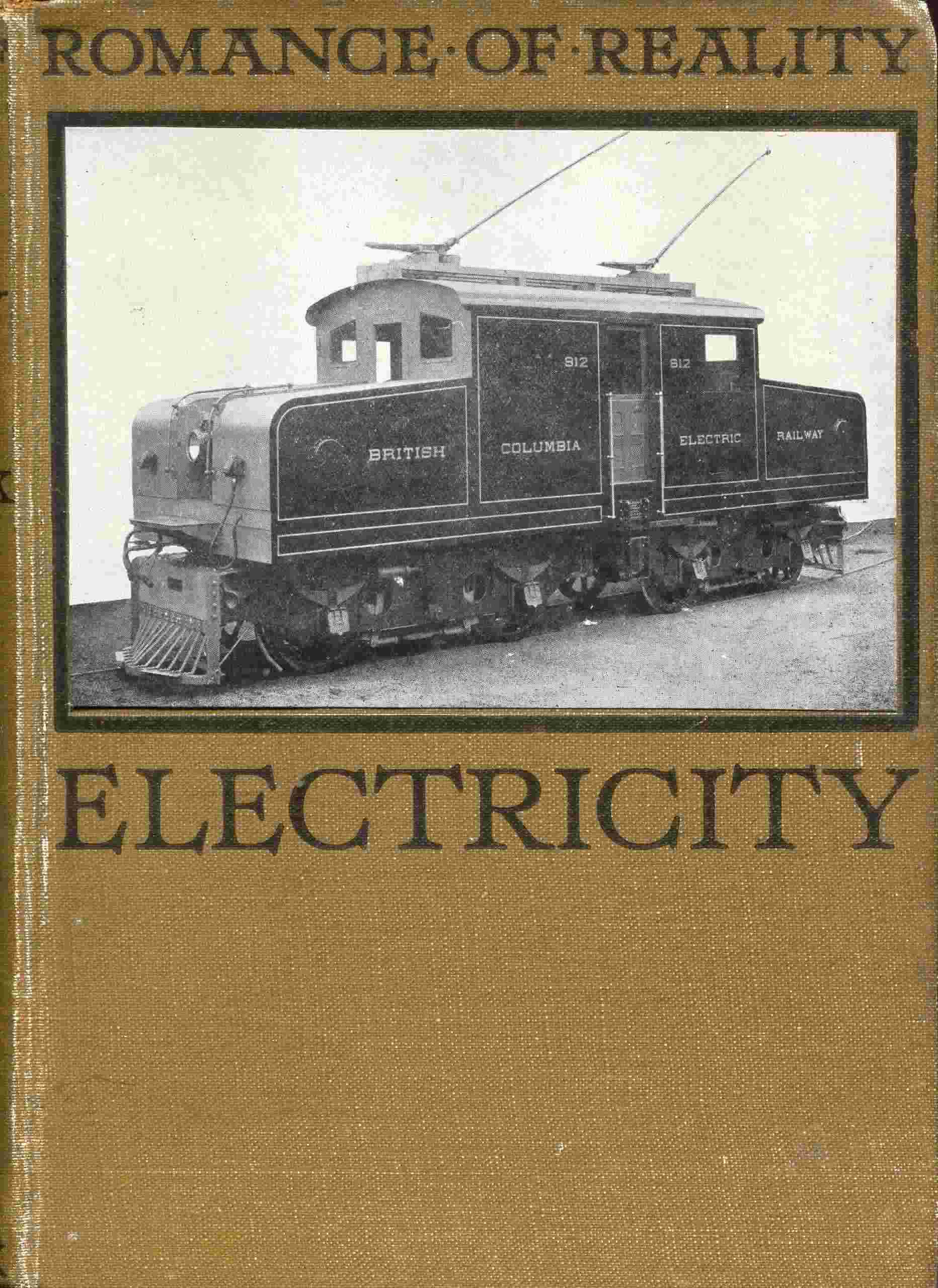
We come now to electric railways. These may be divided into two classes, those with separate locomotives and those without. The separate locomotive method is largely used for haulage purposes in collieries and large works of various kinds. In Plate VII. is seen an electric locomotive hauling a train of coal waggons in a colliery near the Tyne, and it will be seen that the overhead system is used, the trolley arm and wheel being replaced by sliding bows. In a colliery railway it is generally impossible to select the most favourable track from the railway constructor’s point of view, as the line must be arranged to serve certain points. This often means taking the line sometimes through low tunnels or bridges where the overhead wire must be low, and sometimes over public roads where the wire must be high; and the sliding bow is better able than the trolley arm and wheel to adapt itself to these variations. In the colliery where this locomotive is used the height of the overhead wire ranges from 10 feet 6 inches through tunnels or bridges, to 21 feet where the public road is crossed. The locomotive weighs 33½ tons, and has four electric motors each developing 50 horse-power with the current employed. It will be noticed that the locomotive has two sets of buffers. This is because it has to deal with both main line waggons and the smaller colliery waggons, the upper set of buffers being for the former, and the lower and narrower set for the latter. Plate VIII. shows a 50-ton locomotive on the British Columbia Electric Railway, and a powerful locomotive in use in South America. In each case it will be seen that the trolley wheel is used.
In this country electric railways for passenger traffic are mostly worked on what is known as the multiple-unit system, in which no separate locomotives are used, the motors and driving mechanism being placed on the cars themselves. There are also other cars without this equipment, so that a train consists of a single motor-car with or without trailer, or of two motor-cars with trailer between, or in fact of any other combination. When a train contains two or more motor-cars all the controllers, which are very similar to those on electric tramcars, are electrically connected so as to be worked together from one master controller. This system allows the length of the train to be adjusted to the number of passengers, so that no power is wasted in running empty cars during periods of small traffic. In suburban railways, where the stopping-places are many and close together, the efficiency of the service depends to a large extent upon the time occupied in bringing the trains from rest to full speed. In this respect the electric train has a great advantage over the ordinary train hauled by a steam locomotive, for it can pick up speed at three or more times the rate of the latter, thus enabling greater average speeds and a more frequent service to be maintained.
Electric trains are supplied with current from a central generating station, just as in the case of electric tramcars, but on passenger lines the overhead wire is in most cases replaced by a third rail. This live rail is placed upon insulators just outside the track rail, and the current is collected from it by sliding metal slippers which are carried by the cars. The return current may pass along the track rails as in the case of trolley tramcars, or be conveyed by another insulated conducting rail running along the middle of the track.
The electric railways already described are run on continuous current, but there are also railways run on alternating current. A section of the London, Brighton, and South Coast Railway is electrically operated by alternating current, the kind of current used being that known as single-phase. The overhead system is used, and the current is led to the wire at a pressure of about 6000 volts. This current is collected by sliding bows and conveyed to transformers carried on the trains, from which it emerges at a pressure of about 300 volts, and is then sent through the motors. The overhead wires are not fixed directly to the supports as in the case of overhead tramway wires, but instead two steel cables are carried by the supports, and the live wires are hung from these. The effect of this arrangement is to make the sliding bows run steadily and evenly along the wires without jumping or jolting. If ever electricity takes the place of steam for long distance railway traffic, this system, or some modification of it, probably will be employed.
Mention must be made also of the Kearney high speed electric mono-railway. In this system the cars, which are electrically driven, are fitted above and below with grooved wheels. The lower wheels run on a single central rail fixed to sleepers resting on the ground, and the upper wheels run on an overhead guide rail. It is claimed that speeds of 150 miles an hour are attainable with safety and economy in working. This system is yet only just out of the experimental stage, but its working appears to be exceedingly satisfactory.
A self-contained electric locomotive has been constructed by the North British Locomotive Company. It is fitted with a steam turbine which drives a dynamo generating continuous current, and the current is used to drive four electric motors. This locomotive has undergone extensive trials, but its practical value as compared with the ordinary type of electric locomotive supplied with current from an outside source is not yet definitely established.
At first sight it appears as though the electric storage cell or accumulator ought to provide an almost perfect means of supplying power for self-propelled electric vehicles of all kinds. In practice, however, it has been found that against the advantages of the accumulator there are to be set certain great drawbacks, which have not yet been overcome. Many attempts have been made to apply accumulator traction to electric tramway systems, but they have all failed, and the idea has been abandoned. There are many reasons for the failure of these attempts. The weight of a battery of accumulators large enough to run a car with a load of passengers is tremendous, and this is of course so much dead weight to be hauled along, and it becomes a very serious matter when steep hills have to be negotiated. When a car is started on a steep up-gradient a sudden and heavy demand for current is made, and this puts upon the accumulators a strain which they are not able to bear without injury. Another great drawback is the comparatively short time for which accumulators can give a heavy current, for this necessitates the frequent return of the cars to the central station in order to have the batteries re-charged. Finally, accumulators are sensitive things, and the continuous heavy vibration of a tramcar is ruinous to them.
The application of accumulators to automobiles is much more feasible, and within certain limits the electric motor-car may be considered a practical success. The electric automobile is superior to the petrol-driven car in its delightfully easy and silent running, and its freedom from all objectionable smells. On the other hand high speeds cannot be attained, and there is the trouble of having the accumulators re-charged, but for city work this is not a serious matter. Two sets of accumulators are used, so that one can be left at the garage to be charged while the other is in use, the replacing of the exhausted set by the freshly charged one being a matter of only a few minutes. The petrol-driven car is undoubtedly superior in every way for touring purposes. Petrol can now be obtained practically anywhere, whereas accumulator charging stations are comparatively few and far between, especially in country districts; and there is no comparison as regards convenience between the filling of a petrol tank and the charging of a set of accumulators, for one process takes a few minutes and the other a few hours.
Accumulator-driven locomotives are not in general use, but for certain special purposes they have proved very satisfactory. A large locomotive of this kind was used for removing excavated material and for taking in the iron segments, sleepers, rails, and other materials in the construction of the Great Northern, Piccadilly, and Brompton Tube Railway. This locomotive is 50 feet 6 inches long, and it carries a battery of eighty large “chloride” cells, the total weight of locomotive and battery being about 64 tons. It is capable of hauling a load of 60 tons at a rate of from 7 to 9 miles an hour on the level.
Amongst the latest developments of accumulator traction is a complete train to take the place of a steam locomotive hauling a single coach on the United Railways of Cuba. According to the Scientific American the train consists of three cars, each having a battery of 216 cells, supplying current at 200 volts to the motors. Each car has accommodation for forty-two passengers, and the three are arranged to work on the multiple-unit system from one master controller. The batteries will run from 60 to 100 miles for each charging of seven hours.