CHAPTER V
PNEUMATIC COAL-HANDLING PLANTS
The writer was directly interested in the erection and installing of one of the first plants installed in this country for the elevation and conveying of coal, and a description of the various details may give a good idea of a complete plant, handling coal on a commercial scale.
The conditions to be complied with are as follows: 20 tons of “slack” per hour, to be raised 90 ft. above canal level or 80 ft. above road level.
The coal is brought alongside the power-house by canal barges of 25 tons capacity, or by tipping steam waggons from the railway sidings, a distance of one mile away. In both cases the coal is required to be elevated into overhead bunkers of 600 tons capacity placed vertically over the boilers.
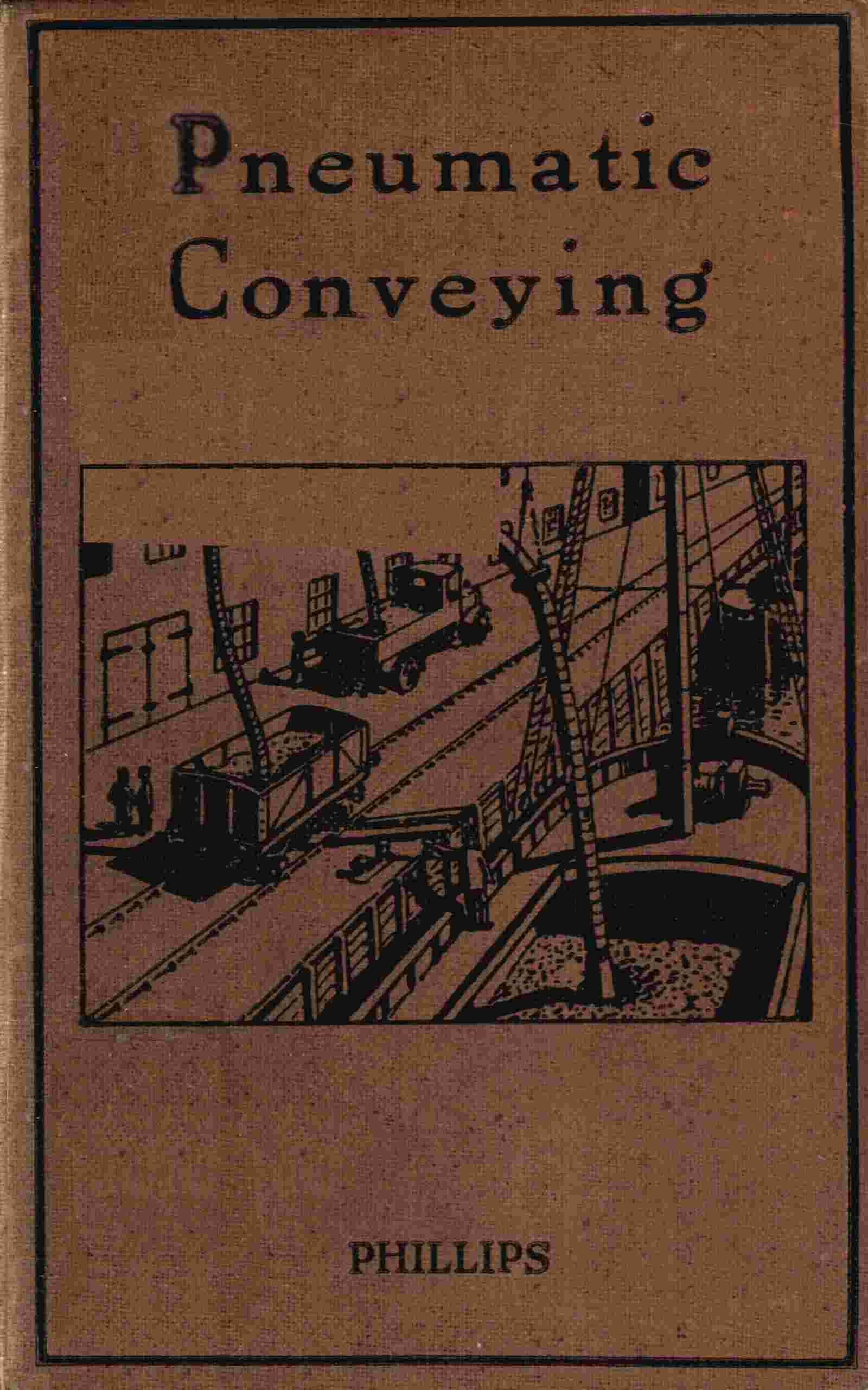
Fig. 23.—Pneumatic Unloading of Coal at Messrs. Boots, Ltd. (Nottingham).
In the first case, immediately the barge is alongside, the flexible suction pipe is lowered into the barge (Fig. 23), and coal immediately begins to rise in the pipe and is discharged as required. Little or no handling of the coal is required after the suction nozzle has once reached the bottom of the barge; all that it is necessary to do is to bring the barge gradually up to the nozzle, the coal then “avalanching” down to the nozzle. Fig. 24 shows the discharger placed on girders over the bunkers into which it discharges continuously. The coal enters at A and the major portion of the fuel is discharged through the rotary valves B.
The coal discharger itself consists of a cast iron vessel with two King’s patent rotating valves. These are designed in the form of a slightly conical taper divided into four sections, one portion of the circular valve being under vacuum, and the other under ordinary atmospheric pressure. The outlet of the valves is larger than the inlet to allow the coal which is in the valve to drop out easily. Over each valve is also provided a four-armed sweeper to prevent any damp coal from forming a cone inside. The discharger is provided with two inlets with full-way bored valves, so that the coal can be drawn either from the water side or from the land side at will. After the coal has been deposited in the main discharger, there is provided a supplementary discharger consisting of a vessel 6 ft. high by 30 ins. diameter, with two inlet pipes of 8 ins. diameter, to provide a contra-flow, so that any particles of coal dust in the air will meet one another in the 30 ins. box at equal velocity and be deposited. The small particles are delivered by a supplementary rotary discharge valve which is set to run very much slower than the main discharger valves.
Fig. 24.—Discharger for Coal Conveying Plant.
The main discharger valves are driven by worm gearing, the latter having one right-hand thread and one left-hand thread, so that the end thrust on the worms is neutralized. Ball bearings are provided and the small motor which drives all three valves is coupled up with an electrical device designed by the author. This device ensures that if anything happens to the top discharge valves—so that the 3 h.p. motor driving them cuts out, owing to an overload or other cause—then the main motor also is cut out by the opening of its circuit breaker. This prevents any “flooding” of the pipes and dischargers.
It may be mentioned that the valves are so designed that a portion of the weight of each valve is carried by the vacuum, so that the vertical wearing lift on the valves when at work is very slight.
The intake pipes for the coal are 5 ins. diameter, and they are provided with heavy cast iron bends, having extra thick metal on the outside radius to allow for the wearing effect of coal passing at the rate of 20 tons per hour.
The pipe into the barge is provided with a flexible steel pipe at the suction nozzle end, for convenience of handling. India-rubber piping has been tried, but the extra cost does not justify its continued use.
The nozzle is made as light as possible for convenience of handling, and is fitted with a special “free air” inlet for the regulation of the amount of air necessary to blend with the coal.
Ash Handling. In addition to unloading coal, the above plant is capable of dealing with hot ashes which are first crushed in a portable clinker breaker, electrically driven, which runs under all the ash hoppers of the boilers. The ash when crushed gravitates into funnel-topped tee-pieces, inserted in the main ash-conveying pipe, whence it is immediately sucked up into an overhead ash hopper to await the convenience of the waggons which dispose of it on the “tips.”
Flue Cleaning. A 3 in. suction pipe has been run round the boiler-house in such positions that flexible hose can be attached for flue cleaning purposes. In this case the cleaners simply use an enlarged nozzle such as is supplied with a domestic equipment and the dust is removed from the flues, economizer soot chambers, etc., into the ash hopper without trouble or dust.
The success of this plant is best indicated by the fact that, at the moment of writing, a duplicate plant is being erected. Owing to the growth of the business, and its demand for power and steam, the original plant has to be worked continuously on coal, so that the ash and flue dust problem has become acute again.
Portable Floating Plant. A third plant ordered by the same firm is of considerable interest. This is intended to be mounted in a barge so as to be portable. Owing to lack of space in close proximity to the power-house, considerable difficulty is found in keeping adequate stocks of coal on the site except the 600 tons in the overhead bunkers. In order to secure continuity of working, it is essential that as much fuel as possible be stored, and for this purpose a coal pile has been made about half a mile away from the works, adjoining the canal. Ashes can be disposed of on certain fields a few miles outside the city in swamps and pools caused by subsidences, due to colliery workings.
The portable plant is therefore arranged to operate as follows: the barge is self-propelled by a 30 h.p. paraffin engine which can be coupled by clutches to either the propeller or a Roots blower, the latter being the exhauster for the portable suction plant.
The barge is loaded with ashes for disposal, and then proceeds under its own power to the site where they are to be dumped. The clutch is operated disconnecting the propeller and operating the blower. The suction side of the blower is coupled up with the pipe line in the boat and the barge feeds the plant by means of the flexible hose: the discharge pipe is raised over the towing path so as not to interfere with passing traffic, and the ashes are blown out into the swamps previously mentioned. It will readily be recognized how simple this unloading becomes compared with trying to dig out the ashes with either a spade or a fork.
The empty barge then returns to the coal pile and takes up a load of coal in a similar manner, then proceeding to the power-house under its own power and being unloaded by the original fixed pneumatic installation in the ordinary way.
The coal arriving by road is tipped into a concrete hopper excavated below the ground level, and so designed with sloping sides that it is self feeding into a suction pipe connected to the bottom of the hopper. The same procedure occurs except that in this case the coal enters the main discharger at the top (E, Fig. 24).
It is interesting to note that the very fine dust collected from the air filter is eagerly sought after by the foundry trade, and what would at first appear to be a waste product impossible to burn, is actually a valuable by-product of the plant.