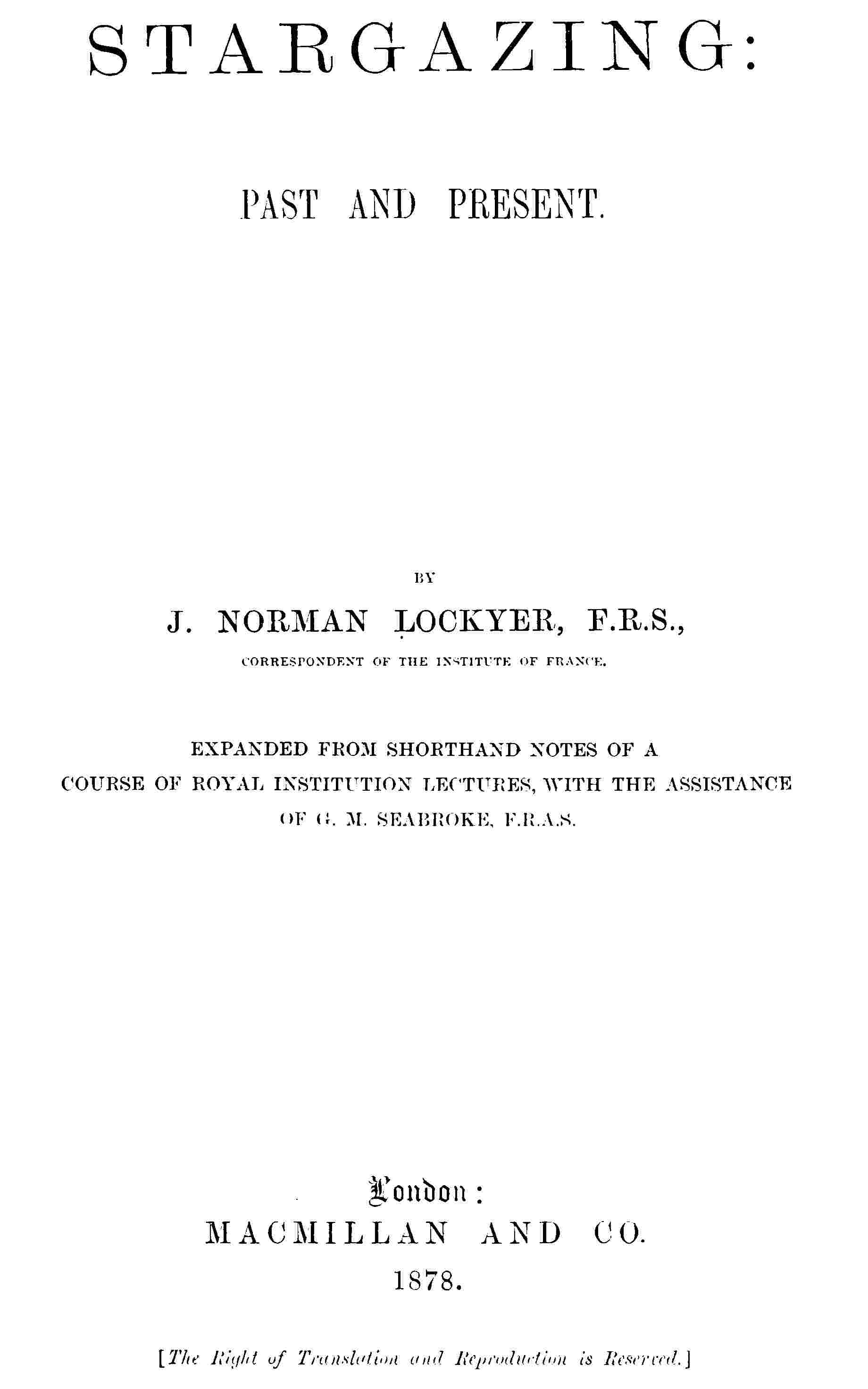
Fig. 45.—Combination of Flint- and Crown-glass Lenses in an Achromatic Lens.
It will not be absolutely colourless, for the reasons which will be now explained. If light be passed through different substances placed in hollow prisms, or through prisms of flint and crown glass, and the spectra thus produced be observed, we find there are important differences. When we expand the spectra considerably, we see that the action of these different substances is not absolutely uniform, some colours extending over the spectrum further than others. In the case of one kind of glass the red end of the spectrum is crushed up, while in the other we have the red end expanded.
This is called the irrationality of the spectrum produced by prisms of different substances. The crown and the flint-glass lenses—and for telescopes we must use such glass—give irrational spectra, so that the achromatic telescope is not absolutely achromatic, in consequence of this peculiarity; for if R, G, B, Fig. 46, are the centres of the red, green, and violet in the spectrum given by a prism composed of the glass of which one lens is made, and R´, G´, B´, are those of the other, if the lenses are placed so as to counteract each other, and are of such curves that the reds and violets are combined, the greens will remain slightly outstanding. Suppose, as in the drawing, the second prism disperses the violet as much as the first one does, then, when these are reversed they will exactly compensate red and violet. But the second one acts more strongly on the green than the first, which will be over-compensated; and if we weaken the second prism so that the green and red are correct, then the violet will be slightly outstanding, which in practice is not much noticed, except with a very bright object when there is always outstanding colour.
Fig. 46.—Diagram Illustrating the Irrationality of the Spectrum.
This is, however, not a matter of any very great importance for ordinary work, since the visual rays all lie in the neighbourhood of the yellow, so that opticians take care to correct their lenses for the rays in this part of the spectrum, and at the same time, as a matter of necessity, over-correct for the violet rays, that is, reverse the dispersion of the exterior lens, so that the violet rays have a longer instead of a shorter focus than the red, and, therefore, in looking at a bright object, such as a first magnitude star, it appears surrounded by a violet halo; with fainter objects the blue light is not of sufficient intensity to be visible. It is, therefore, always preferable to correct for the most visible rays and leave the outstanding violet to take care of itself; but nevertheless various proposals have been made to get rid of it. Object-glasses containing fluids of different kinds have been tried, but they have never become of any practical value, and it does not seem probable that they ever will.
In order to get rid of the outstanding violet colour when the remainder of the spectrum was corrected, Dr. Blair constructed object-glasses the space between the lenses of which were filled with certain liquids, generally a solution of a salt of mercury or antimony, with the addition of hydrochloric acid; for in the spectrum given by the metallic solution the green is proportionally nearer the red than is the case with the spectrum produced by hydrochloric acid, so that by the adjustment of the different solutions he exactly destroyed the outstanding colour of the ordinary combination. In this way Sir John Herschel tells us he was able to construct lenses of three inches aperture and only nine inches focal length, free from chromatic and spherical aberration.
It was proposed by Mr. Barlow to correct a convex crown-glass lens for chromatic aberration by a hollow concave lens containing bisulphide of carbon, a highly dispersive fluid, having double the power of flint glass. This lens was placed in the cone of rays between the object-glass and the eyepiece. Its surfaces were concavo-convex, calculated to destroy spherical aberration, and its distance from the object-glass was varied until exact achromatism was obtained. A telescope of this principle of eight inches aperture was made by Mr. Barlow, which proved highly satisfactory. In the early part of the last century it was proposed by Wolfius to interpose between the object-glass and eyepiece a concave lens in order to give greater magnification of the image, with a slight increase of focal length; if an ordinary lens be used the achromatism of the images given by the object-glass will be destroyed. Messrs. Dolland and Barlow, however, proposed to make the concave lens achromatic, so that the image is as much without colour when the lens is used as without it. Mr. Dawes found such a lens to work extremely well. These lenses, usually called “Barlow lenses,” are generally made about one inch in diameter, and by varying their distance from the eyepiece the image is altered in size at pleasure.
In the reflecting telescope, with which we will now proceed to deal, there is an absence of colour; but the reflector is not without its drawbacks, for there are imperfections in it as great as those we have been considering in the case of the refractor.
CHAPTER VII.
THE REFLECTION OF LIGHT.
We have now dealt with the refraction of light in general, including deviation and dispersion, in order to see how it can assist us in the formation of the telescope; and we have shown how the chromatic effect of a single lens can be got rid of by employing a compound system composed of different materials, and so we have got a general idea of the refracting telescope. We have now to deal with another property of light, called reflection; and our object is to see how reflection can help us in telescopes.
In the case of reflection we get the original direction of the ray changed as in the case of refraction, but the deviation is due to a different cause. Take a bright light, a candle will do, and a mirror fixed so that the light falls on its surface and is thrown back to the eye, Fig. 47, we see the image of the candle apparently behind the mirror; the rays of light falling on the mirror are reflected from it at exactly the same angle at which they reach it. This brings us in the presence of the first and most important law of reflection; and it is this, at whatever angle the light falls on a mirror, at that angle will it be reflected. As it is usually expressed, the angle of incidence, which is the angle made by the incident ray with an imaginary line drawn at right angles to the mirror, called the normal, is equal to the angle of reflection, that is, the angle contained by the reflected ray, and the normal to the surface. In order, therefore, to find in what direction a ray of light will travel after striking a flat polished surface, we must draw a line at right angles to the surface at the point where the ray impinges on it, then the reflected ray will make an angle with the normal equal to that which the incident ray makes, or the angles of incidence and reflection will be equal.
Fig. 47.—Diagram Illustrating the Action of a Reflecting Surface.
Very simple experiments, which every one can make will show us the laws which govern the phenomena of reflection. Let us employ a bath of mercury for a reflecting surface, and for a luminous object a star, the rays of which, coming from a distance which is practically infinite, to the surface of the earth, may be considered exactly parallel. The direction of the beams of light coming from the star, and falling on the mirror formed by the mercury, is easily determined by means of a theodolite, Fig. 48. If we look directly at the star, the line I´ S´ of the telescope indicates the direction of the incident luminous rays, and the angle S´ I´ N´, equal to the angle S, I, N, is the angle of incidence, that is to say, that formed by the luminous ray with the normal to the surface at the point of incidence.
Fig. 48.—Experimental Proof that the Angle of Incidence = Angle of Reflection.
In order to find the direction of the reflected luminous rays, we must turn the telescope on its axis, until the rays reflected by the surface of the mercury bath enter it and produce an image of the star. When the image is brought to the centre of the telescope, it is found that the angle R´ I´ N´ is equal to the angle of reflection N, I, R. Thus, in reading the measure on the graduated circle of the theodolite the angle of reflection can be compared with the angle of incidence.
Now, whatever may be the star observed, and whatever its height above the horizon, it is always found that there is perfect equality between these angles. Moreover, the position of the circle of the theodolite which enables the star and its image to be seen evidently proves that the ray which arrives directly from the luminous point and that which is reflected at the surface of the mercury are both in the same vertical plane.
Now this demonstrates one of the most important laws of reflection. The laws of refraction do not deal directly with the angles themselves, but with the sines of the angles; in reflection the angles are equal; in refraction the sines have a constant relation to each other.
So far we have dealt with plane surfaces, but in the case of telescopes we do not use plane surfaces, but curved ones, so we will proceed at once to discuss these.
Fig. 49.—Convergence of Light by Concave Mirror.
Fig. 50.—Conjugate Foci of Convex Mirror.
In Fig. 49, A represents a curved surface, such as that of a concave mirror, the centre of curvature being C. Now we can consider that this curved surface is made up of an infinite number of small plane surfaces, and since all lines drawn from the centre, C, to the mirror, will be at right angles to the surface at the points where they meet it, we find, from our experiment with the plane mirror, that rays falling on the mirror at these points will be reflected so that the angles on either side of each of these lines shall be equal; so, for instance, in Fig. 49, we wish to find to what point the upper ray will be reflected, and we draw a line from the centre, C, to the point where it falls on the mirror, and then draw another line from that point making the angle of reflection equal to that made by the incident ray, and we can consider the small surface concerned in reflection flat, so that the ray will in this case be reflected to F. If now we take any other ray, and perform the same operation we shall find that it is also reflected nearly to F, and so on with all other parallel rays falling on the mirror; and this point, F, is therefore said to be the focus of the mirror. If now the rays, instead of falling parallel on the mirror, as if they came from the sun or a very distant object, are divergent, as if they came from a point S, Fig. 50, near the mirror, the rays approach nearer to the lines drawn from the centre to the mirror, one of which is represented by the dotted line; or, in other words, the angles of incidence become reduced, and so the angles of reflection will also be reduced, and the focus of the rays from S will approach the centre of the mirror, and be at s; just so it will be seen that if an illuminated point be at s, its focus will be at S, and these two points are therefore called conjugate foci.
Fig. 51.—Formation of Image of Candle by Reflection.
Fig. 52.—Diagram explaining Fig. 51.
If a candle is held at a short distance in front of a concave mirror, as represented in Fig. 51, its image appears on the paper between the candle and the mirror, so that the rays from every point of the flame are brought to a focus, and produce an image just as the image is produced by a convex lens. If we study Fig. 52 the formation of this image will be clearly understood. First we must note that the rays A, C, a, and B, C, b, which pass through the centre of curvature of the mirror C, will fall perpendicularly on the surface, and be reflected back on themselves, so that the focus of the part a of the arrow will be somewhere on A a, and that of B on B b, and by drawing another ray we shall find it reflected to a, which will be the focus of the point A, and so also by drawing another line from B, we shall find it is reflected to b, which is the focus of the part B; and we might repeat this process for every part of the arrow, and for every ray from those parts. We now see that since the rays A a and B b cross each other at C, the distance from a to b bears the same proportion to the distance from A to B as their respective distances from the point C; or, in other words, the image is smaller than the object in the same proportion as the distance from the image to C is smaller than the distance from the object to C. Now, in dealing with the stars, which are at a practically infinite distance, the rays are parallel, and will be brought to a focus half-way between the mirror and its centre of curvature. In this case, therefore, the distance from the image to the mirror is equal to that from the image to the centre, so that we can express the size of the image by saying that it is smaller than the object, in proportion as its distance from the mirror is smaller than the distance of the object from C; and as it makes little difference whether we measure the distance of the stars from C or from the mirror, and as C is not always known, we can take the relation of the distances of the object and image from the mirror as representing the proportionate sizes of the two.
We will now consider the case of rays falling on a mirror curved the other way, that is, a convex mirror. Let us consider the ray impinging at D, Fig. 53, which would go on to C, the centre of the mirror. Now, as C D is drawn from the centre, it is at right angles to the mirror at D, and the ray L D, being in the same straight line on the opposite side, will also be at right angles, and will be reflected back on itself. Now take the ray I A, draw C E through A, then E A will be perpendicular to the surface at A, and I A E will be the angle of incidence, and E A G the angle of reflection, so that this ray A G will be reflected away from L D, and so will all the other rays falling on the mirror as K B: and if we continue the lines G A and H B backwards, they will meet at M, and therefore the rays diverge from the mirror as if they came from a point at M, and this point is called the virtual focus.
Fig. 53.—Reflection of Rays by Convex Mirror.
So much for parallel rays. Next let us consider another case which happens in the telescope, namely, where converging rays fall on a convex mirror, as in Fig. 53, where we consider the light proceeding to the mirror from a converging lens along the lines H B and G A, these will be made parallel, at B K and A F, after reflection, and it is manifest that by making the mirror sufficiently convex, these rays, tending to come to a focus at M, could be rendered divergent; and if the curvature is decreased by making the centre of curvature at a certain distance beyond C, it will be seen at once by the diagram that these rays will after reflection, converge towards L and will come to a focus in front of the mirror at a point further in front than C is behind it, so that they have been rendered less convergent only by the mirror in this supposed case.
It will be seen from what has been stated here and in Chapter V., that we get nearly the same results from reflection as we did from refraction when we were considering the functions of glasses instead of mirrors; that a concave mirror acts exactly as a convex lens, and vice versâ, so that they can be substituted the one for the other. If we take a mirror, and allow the light to fall on it from a lamp, no one will have any difficulty in seeing that the mirror grasps the beam, and forms an image which is seen distinctly in front of the mirror, just as one gets an image from a convex lens behind it.
CHAPTER VIII.
THE REFLECTOR.
The point we have next to determine is how we can utilise the properties of reflection for the purposes of astronomical observation. Many admirable plans have been suggested. The first that was put on paper was made by Gregory, who pointed out that if we had a concave mirror, we should get from this mirror an image of the object viewed at the focus in front of it, as in Fig. 51. Of course we cannot at once utilise this focal image by using an eyepiece in the same way as we do in a refractor, because the observer’s head would stop the light, and the mirror would be useless, and all the suggestions which have been made, have reference to obtaining the image in such a position that we are able to view it conveniently.
Gregory, the Scottish astronomer above referred to, in 1663 suggested a method, and it has turned out to be a good one, of utilizing reflection by placing a small mirror D C, Fig. 54, on the other side of the focus A of the large one, at such a distance that the image at A is again focussed at B by reflection from the small mirror; and at B we get of course an enlarged image of A. The rays of light proceeding to B would, however, be intercepted by the large mirror, unless an aperture were made in the large mirror of the size of the small one through which the rays could pass and be rendered parallel by means of an eyepiece placed just behind the large mirror. So that towards the object is the small mirror C, and there is an eyepiece E, which enables the image of the object to be viewed after two reflections, first from the large mirror and then from the small one. Mr. Short (who made the best telescopes of this construction, and did much for the optical science of the last century) altered the position of the small mirror with reference to the focus of the large one, by sliding it along the tube by a screw arrangement, F, and so was enabled to focus both near and distant objects without altering the eyepiece.
Fig. 54.—Reflecting Telescope (Gregorian).
But before this was put into practice, Sir Isaac Newton (in 1666) made telescopes on a totally different plan.
The eyepiece of the Newtonian telescope is at the side of the tube, and not at the end, as in Gregory’s. We have next to inquire how this arrangement is carried out, and, like most things, it is perfectly simple when one knows how it is done. There is a large mirror at the bottom of the tube as in the Gregorian, but not perforated, and the focus of the mirror would be somewhere just in front of the end of the tube. Now in this case we do not allow the beam to get to the focus at all in the tube or in front of it; but before it comes to the focus it is received on a small diagonal plane surface m, and thus it is at once thrown outwards at right angles through the side of the tube, and comes to a focus in front of an eyepiece, placed at the side, ready to be viewed the same as an image from a refractor (Fig. 55).
Fig. 55.—Newton’s Telescope.
The next arrangement is one which Mr. Grubb has recently rescued from obscurity, and it is called the Cassegrainian form. It will be seen on referring to that, Fig. 56, if the small mirror, C, were removed, the rays from the mirror A B would come to a focus at F.
In the Gregorian construction a concave reflector was used outside that focus (at C, Fig. 54), but Cassegrain suggested that if, instead of using a concave reflector outside the focus, a reflector with a convex surface were placed inside it, we should arrive at very nearly the same result, provided we retain the hole in the large mirror. The converging rays from A B will fall on the convex surface of the mirror C, which is of such a curvature and at such a distance from F, the focus of the large mirror, that the rays are rendered less converging, and do not come to a focus until they reach D, where an image is formed ready to be viewed by the eyepiece E. It appears from this, that the convex mirror is in this case acting somewhat in the same manner as the concave lens does in the Galilean telescope.
Fig. 56.—Reflecting Telescope (Cassegrain).
Fig. 57.—Front View Telescope (Herschel).
Then, lastly, we have the suggestion which Sir William Herschel soon turned into more than a suggestion. The mirror M in this arrangement is placed at the bottom of the tube as in the other forms, but, instead of being placed flat on the bottom it is slightly tipped, so that if the eyepiece is placed at the edge of the extremity of the tube all parallel rays falling on the mirror are reflected to the side of the tube at the top where the eyepiece is, instead of being reflected to a convex or other mirror in the middle.
This is called the front view telescope, and it enabled Sir William Herschel to make his discoveries with the forty-feet reflector. With small telescopes this form could not be adopted, as the observer’s head would cover some part of the tube and obstruct the light, but with large telescopes the amount of light stopped by the head is small in proportion to what would be lost by using a small mirror.
These are in the main the four methods of arranging reflecting telescopes—the Gregorian, the Cassegrainian, the Newtonian, and the Herschelian.
In order to make large reflectors perfect—large telescopes of short focus, because that is one of the requirements of the modern astronomer—we have to battle against spherical aberration.
We have already seen that the power of substances to refract light differs for different colours, and we have seen the varied refraction of different parts of the spectrum, and the necessity of making lenses achromatic. Now there is one enormous advantage in favour of the reflector. We do not take our light to bits and put it together again as with an achromatic lens. But curiously enough, there is a something else which quite lowers the position of the reflector with regard to the refractor. Although, in the main all the light falling in parallel lines on a concave surface is reflected to a focus, this is only true in a general sense, because, if we consider it, we find an error which increases very rapidly as the diameter of the mirror increases or as the focal length diminishes. For instance, D I, Fig. 58, is the segment of a circle, or the section of a sphere—if we deal with a solid figure. D C, E G and H I, are three lines representing parallel rays falling on different parts of it. According to that law which we have considered, we can find where the ray E G will fall. We draw a line L, G, from the centre to the point of reflection, and make the angle F G L, equal to the angle of incidence E G L; then F will be the focus, so far as this part of the mirror is concerned. Now let us repeat the process for the ray H I, and we shall find that it will be reflected to K, a point nearer the mirror than F, and it will be seen that the further the rays are from the axis D C, the further from the point F is the light reflected; so that if we consider rays falling from all parts of the reflecting surface, a not very large but a distinctly visible surface is covered with light, so that a spherical surface will not bring all the rays exactly to a point, and with a spherical mirror we shall get a blurred image. We can compare this imperfection of the reflector, called spherical aberration, with the chromatic aberration of the object-glass.
Fig. 58.—Diagram Illustrating Spherical Aberration.
Fig. 59.—Diagram Showing the Proper Form of Reflector to be an Ellipse.
Newton early calculated the ratio of imperfection depending upon these properties of light, first of dispersion and then of spherical aberration, and he found that in the refracting telescope the chromatic aberration was more difficult to correct and get rid of than the spherical aberration of the reflector, so that in Newton’s time, before achromatic lenses were constructed, the reflector with its aberration had the advantage. It must now be explained how this difficulty is got over. What is required to produce a mirror capable of being used for astronomical purposes, is to throw back the edges of the mirror to the dotted line A C I, Fig. 58, which will make the margin of the mirror a part of a less concave mirror, and so its focus will be thrown further from itself—to F, instead of to K. Now let us consider what curve this is, that will throw all the rays to one point. It is an ellipse, as will be seen by reference to Fig. 59, in which, instead of having a spherical surface the section of which is a circle, we deal with a surface whose section is an ellipse.
It will be seen in a moment, that by the construction of an ellipse any light coming in any direction from the point A, which represents one of the foci of the curve, must necessarily be reflected back to the other focus, B, of the curve, for it is a well-known property of this curve that the angles made with a tangent C D, by lines from the foci are equal; and the same holds good for the angles made at all other tangents; and it will be seen at once that this is better than a circular curve, because by making the distance between the foci almost infinite we shall have the star or object viewed at one focus and its image at the other; if we use any portion of the reflecting surface we shall still get the rays reflected to one point only. It must also be noticed, that unless we have an ellipse so large that one focus shall represent the sun or a particular star we want to look at, this curve will not help us in bringing the light to one point, but if we use the curve called the parabola, which is practically an ellipse with one focus at an infinite distance, we do get the means of bringing all the rays from a distant object to a point. Hence the reflector, especially when of large diameter, is of no use for astronomical purposes without the parabolic curve.
That it is extremely difficult to give this figure may
be gathered from Sir John Herschel’s statement, that
in the case of a reflecting telescope, the mirror of
which is forty-eight inches in diameter and the focal
distance of which is forty feet, the distance between
the parabolic and the spherical surface, at the edges
of the mirror, will be represented by something less
than a twenty-one thousandth part of an inch, or, more
accurately, 1
21333 inch. In Fig. 58 the point A represents
the extreme edge of the curve of the parabolic mirror,
and D that of the circular surface before altered into a
parabola.
At the time of Sir William Herschel the practical difficulties in constructing large achromatic lenses led to the adoption by him of reflectors beginning with small apertures of six inches to a foot, and increasing till he obtained one of four feet in diameter and forty-six feet focal length. This has been surpassed by Lord Rosse, whose well-known telescope is six feet diameter, and fifty-three feet focal length. Mr. Lassell, Mr. De La Rue, M. Foucault and Mr. Grubb, have also more recently succeeded in bringing reflectors to great perfection.
How the work has been done will be fully stated in the sequel.
CHAPTER IX.
EYEPIECES.
We have considered the telescope as a combination of an object-glass and eyepiece in the one case, and of a speculum and eyepiece in the other; that is to say, we have discussed the optical principles which are applied in the construction of refracting and reflecting telescopes, the telescope being taken as consisting of an object-glass or speculum and an eyepiece of the most simple form, viz., a simple double convex lens.
We must now go into detail somewhat on the subject of eyepieces, and explain the different kinds.
It will be recollected that when we spoke of the object-glass, its aberration, both chromatic and spherical, was mentioned. Now every ordinary lens has these errors, and eyepieces must be corrected for them, but this is not done in exactly the same way as with object-glasses.
In the case of eyepieces the error is corrected by using two lenses of such focal lengths or at such a distance apart that each counteracts the defects of the other; not by using two kinds of glass as in the case of the object-glass, but by so arranging the lenses that the coloured rays produced by the first lens shall fall at different angles of incidence on the second and become recombined.
Fig. 60.—Huyghens’ Eyepiece.
Let us take the case of a well-known eyepiece, called the Huyghenian eyepiece, after its inventor. It consists of two plano-convex lenses, A and B Fig. 60, with their convexities turned towards the object-glass, and having their focal lengths in the proportion of three to one. The strongest lens, A, being next the eye, the lens B is placed inside the focus of the object-glass, so that it assists in bringing the image, say of a double star, to a focus at F, half way between the lenses, and nearer to the object-glass than it would have been without the lens. This image is then viewed by the eye-lens, A, and a magnified image of it seen apparently at F´, as has been before explained. Now let us see how the fieldlens renders this combination achromatic. Let us consider the path of a ray falling on the lens near B, shown in section in Fig. 61: it is there refracted, but, the blue rays being refracted more than the red, there will be two rays produced, r and v, giving of course a coloured edge to the image; but when this image is viewed by the eye-glass, A, it no longer appears coloured, for the ray v, falling nearer the axis of A, is less bent than r, and they are rendered nearly parallel and appear to proceed from the point F´ where the whole image appears without colour. In order to get the best result with this form of eyepiece the focal length of the fieldlens should be three times that of the eye-lens and they should be placed at a distance of half their joint focal lengths apart.
Fig. 61.—Diagram Explaining the Achromaticity of the Huyghenian Eyepiece.
The next eyepiece which comes under consideration is that called Ramsden’s, Fig. 62. It consists of two plano-convex lenses of the same focus, A and B, placed at a distance of two-thirds of the focal length of either apart; they are both on the eye side of the focus of the telescope, and act together, to render the rays parallel and give a magnified virtual image of F´F.
This eyepiece is not strictly achromatic, but it suffers least of all lenses from spherical aberration; it also has the advantage of being placed behind the focus of the object-glass, which makes it superior to others in instruments of precision, as we shall presently see.
Fig. 62.—Ramsden’s Eyepiece.
It must be remembered that these eyepieces give an inverted image—or rather the object glass gives an inverted image, and the eyepiece does not right it again; but there are eyepieces that will erect the image, and Rheita’s is one of this kind. It is, as will be seen from Fig. 63, merely a second application of the same means that first inverts the object, namely, a second small telescope. A is the object-glass, a b the image inverted in the usual way; B is an ordinary convex lens sending the rays from a and b parallel. Now, instead of placing the eye at C, as in the ordinary manner, another small lens, acting as an object-glass, is placed in the path of the rays, bringing them to a focus at a´, b´, and forming there an erect image which is viewed by the eye-lens D. This is the erecting eyepiece or “day eyepiece,” of the common “terrestrial telescope.” Dollond substituted an Huyghenian eyepiece for the eye-lens D, and so made what is called his four-glass eyepiece.
Dr. Kitchener devised and Mr. G. Dollond made an alteration in this eyepiece in order to vary its power at pleasure. It is done in this way: The size of the image a´ b´ depends upon the relation of the distances a B and E a´, which can be varied by altering the distance of the combination of the lenses B and E, from the image a b, and so making a´ b´ larger and at a focus further from E; the tube carrying d slides in and out, so that it can be focussed on a´ b´ at whatever distance from E it may be. This arrangement is called Dollond’s Pancratic eyepiece.
Fig. 63.—Erecting or day eyepiece.
On the sliding tube carrying the lens D, or rather the Huyghenian eyepiece in place of the single lens, are marked divisions, showing the power of the eyepiece when drawn out to certain lengths, so that if we want the eyepiece to magnify say 100 times, the tube carrying the eye-lens is drawn out to the point marked 100, and the whole eyepiece moved in or out of the telescope tube by the focussing screw, until the image of the object viewed is focussed in the field of the eyepiece D. To increase the power, we have only to draw out the eyepiece D, and move the whole combination nearer to the object-glass so as to throw the image a´ b´ further from the lens E. This eyepiece, though so convenient for changing powers, is little used, owing perhaps chiefly to four lenses being required instead of two, hence a loss of light, so a stock of eyepieces of various powers is generally found in observatories. When very high powers are required, a single plano-convex lens is sometimes used, but although there is less loss of light in this case, the field of view is so contracted in comparison with that given with other eyepieces that the single lens is seldom used. This form is, however, adopted in Dawes’ solar eyepiece, to be hereafter mentioned, and a number of lenses are in this case fixed in holes near the circumference of a disc of metal which turns on its centre, so that by rotating the disc the lenses come in succession in front of the focus of the object-glass, and the power can be changed almost instantaneously.
In order that objects near the zenith may be observed with ease, a diagonal reflector is sometimes used, so that the eye looks sidewise into the telescope tube instead of directly upwards. This reflector may take the form of two short pieces of tube joined together at right angles, and having a piece of silvered glass or a right-angled prism at the angle, so that when one tube is screwed into the telescope, the rays of light falling on the reflector are sent up the other, in which the ordinary eyepiece is placed.
The eyepieces just described are suitable, without further addition, for observing all ordinary objects, but when the sun has to be examined a difficulty presents itself. The heat rays are brought to a focus along with those of light, and with an object-glass of more than one or two inches aperture there is great danger of the heat cracking the lenses, but with such telescopes the interposition—and neglect of this may cost an eye—of smoked or strongly-coloured glass in front of the eye is generally sufficient to protect it from the intense glare. With larger telescopes, however, dark glasses are apt to split suddenly and allow the full blaze of sunlight to enter the eye and do infinite mischief, and some other method of reducing the heat and light is required. Perhaps the most simple method of effecting this object is to allow the light to fall on a diagonal plane glass reflector at an angle of 45°, which lets the greater part of the light and heat pass through, reflecting only a small portion onwards to the eyepiece and thence to the eye; a coloured glass is, however, required as well, and the glass reflector must form part of a prism of small angle, otherwise there will be two images, one produced by each surface.
Another arrangement is to reflect the rays from the surfaces of two plates of glass inclined to them at the polarizing angle, so that by turning the second plate, or a Nicols’ prism, in its place round the ray as an axis, the amount of light allowed to pass to the eye can be varied at pleasure.
The late Mr. Dawes constructed a very convenient solar eyepiece, depending on the principle of viewing a very small portion of the sun’s image at one time, and thereby diminishing the total quantity of heat passing through the eye-lens. The details of the eyepiece are as follows: very minute holes of varying diameters are made in a brass disc near its circumference, and as this is turned each successive hole is brought into the centre of the field of view and the common focus of the eye-lens and object-glass. Small areas on the sun of different sizes can thus be examined at pleasure. A number of eye-lenses of different powers arranged in a disc of metal can be successively brought to bear, giving a means of quickly varying the power, while coloured glasses of different shades can be passed in front of the eye in the same manner. The surface of the disc of brass containing the holes is covered on one side—that on which the sun’s image falls—with plaster of Paris, which, being a bad conductor, prevents the heat from affecting the whole apparatus.
The true magnifying power of the eyepiece is found by dividing the focal length of the object-glass by that of the eyepiece; in practice it is found approximately by comparing the diameter of the object-glass with that of its image formed by the eyepiece when the telescope is in its usual adjustment; the former divided by the latter giving the power required. The diameter of the image can be measured by a small compound microscope carrying a transparent scale in its focus, when the image of the object-glass is brought to a focus and enlarged on the scale and then viewed, together with the divisions, by the microscope; or the image can be measured with tolerable accuracy by Mr. Berthon’s dynameter, consisting of a plate of metal traversed longitudinally by a wedge-shaped opening. This is placed close to the eye-lens in the case of the Huyghenian eyepiece, or at the point where the image of the object-glass is focussed with other forms of eyepieces, and the plate moved until the sides of the wedge-shaped opening are exactly tangential to the image; the point of the opening at which this occurs is read off on a scale, which gives the width of opening at this point and therefore the diameter of the image.