16. It is not too much to say that the duty on glass entirely stifled, if indeed it did not kill, the optical art in England. We were so dependent for many years upon France and Germany for our telescopes, that the largest object-glasses at Greenwich, Oxford, and Cambridge are all of foreign make.
17. These details are given from the Forces of Nature (Macmillan).
CHAPTER XXI.
THE ADJUSTMENTS OF THE EQUATORIAL.
As the equatorial is par excellence the amateur’s instrument, and as in setting up an equatorial it is important that the several adjustments should be correctly made, they are here dwelt upon as briefly as possible. They are six in number.
1. The inclination of the polar axis must be the same as that of the pole of the heavens.
2. The declination circle must read 0° when the telescope is at right angles to the polar axis.
3. The polar axis must be placed in the meridian.
4. The optic axis of the telescope, or line of collimation must be at right angles to the declination axis, so that it describes a great circle on moving about that axis.
5. The declination axis must be at right angles to the polar axis, in order that the telescope shall describe true meridians about that axis.
6. The hour circle must read 0h. 0m. 0sec. when the telescope is in the meridian.
When these are correctly made the line of collimation will, on being turned about the declination axis, describe great circles through the pole, or meridians, and when moved about the polar axis, true parallels of declination; and the circles will give the true readings of the apparent declination, and hour angles from the meridian.
To make these adjustments, the telescope is set up by means of a compass and protractor, or otherwise in an approximately correct position, the declination circle put so as to read nearly 90° when the telescope points to the pole, and the hour circle reading 0h. 0m. 0sec. when the telescope is pointing south.
First, then, to find the error in altitude of the polar axis.
Take any star from the Nautical Almanac of known declination on or near the meridian, and put an eyepiece with cross wires in it in the telescope, and bring the star to the centre of the field as shown by the wires. Then read the declination circle, note the reading down and correct it for atmospheric refraction, according to the altitude[18] of the star by the table given in the Nautical Almanac, turn the telescope on the polar axis round half a circle so that the telescope comes on the other side of the pier. The telescope is then moved on its declination axis until the same star is brought to the centre of the field, and the circle read as before and corrected. The mean of the two readings is then found, and this is the declination of the star as measured from the equator of the instrument, and its difference from the true declination given by the almanac is the error of the instrumental equator and of course, also of the pole at right angles to it.
It is obvious that if the declination circle were already adjusted to zero, when the telescope was pointing to the equator of the instrument, one observation of declination would determine the error in question; and it is to eliminate the index error of the circle, as it is called, that the two observations are taken in such a manner that the index error increases one reading just as much as it decreases the other, so that the mean is the true instrumental declination.
Index Error.—From what has just been stated it follows that half the difference of the two readings is the index error, which can be at once corrected by the screws moving the vernier, giving correction No. 2.
To correct the error in altitude of the pole, the circle is then set to the declination of the star given by the almanac, corrected for refraction, and the telescope brought above or below the star as the error may be, and the polar axis carrying the telescope is moved by the setting screws, until the star is in the centre of the field.
3rd Adjustment.—A single observation of any known star, about 6 hours to the east or west will give the error of the polar axis east and west, the difference between the observed and true declination being this error, and it can be corrected in the same manner as the last. These observations should be repeated, and stars in different parts of the heavens observed, in order to eliminate errors of division of the circle until the necessary accuracy is obtained.
For example:
| Observed dec. of Capella | 43° | 50´ | 30˝ | Telescope west. | |||
| 47° | 0´ | 0˝ | Telescope east. | ||||
| ——— | ——— | ——— | |||||
| 2) | 90° | 50´ | 30˝ | ||||
| ——— | ——— | ——— | |||||
| 45° | 25´ | 15˝ | 47° | 0´ | 0˝ | ||
| Error due to refraction | 0° | 0´ | 7˝ | 43° | 50´ | 30˝ | |
| ——— | ——— | ——— | ——— | ——— | ——— | ||
| Instrumental declination | 45° | 25´ | 8˝ | 2) | 3° | 9´ | 30˝ |
| True declination | 45° | 52´ | 0˝ | ——— | ——— | ——— | |
| ——— | ——— | ——— | Index error | 1° | 34´ | 45˝ | |
| 26´ | 52˝ |
This indicates that the pole of the instrument is pointing below the true pole, and index error 1° 34´ 45˝.
| Observed declination of Pollux 6h. west | 28° | 19´ | 18˝ |
| Refraction | 0° | 0´ | 46˝ |
| ——— | ——— | ——— | |
| 28° | 18´ | 3˝ | |
| True declination | 28° | 20´ | 10˝ |
| ——— | ——— | ——— | |
| 0° | 1´ | 38˝ |
This shows the pole to be 1´ 38˝ east of true pole.
4th Adjustment.—For the estimation and correction of the third error, that of collimation, an equatorial star is brought to the centre of the field of the telescope, the time by a clock noted, and the hour circle read. The polar axis is then turned through half a circle, and the star observed with the telescope on the opposite side (say the west) of the pier, the time noted, and the hour circle read. Subtract the first reading from the second (plus twenty-four hours if necessary) and subtract the time elapsed between them, and the result should be exactly twelve hours, and half the difference between it and twelve hours is the error in question. If it is more than twelve hours the angle between the object end of the telescope and the declination axis is acute, and if less then it is obtuse. This error can then be corrected by the proper screws. A little consideration will show, that if the angle between the object end of the telescope and the declination axis be acute, and the telescope is on the east side of the pier, and pointing to a star, say on the meridian, the hour circle will not read so much as it would do if the line perpendicular to the declination axis were pointing to the meridian. When the telescope is on the wrest side of the pier, the circle will read higher for the same reason, and therefore the difference between the angle through which the hour circle is moved and 180° is equal to double the angle between the line perpendicular to the declination axis and the collimation axis of the telescope; allowance being made for the star’s motion.
For example γ Virginis, Dec. 0° 46´·5.
| Time by clock. | Hour circle reading. | |||||
|---|---|---|---|---|---|---|
| 11h. | 23m. | 52s. | 11h. | 55m. | 30s. | Telescope east. |
| 11h. | 31m. | 55s. | 24h. | 8m. | 24s. | Telescope west. |
| ———— | ———— | ———— | ———— | ———— | —————— | |
| 8m. | 3s. | 12h. | 12m. | 54s. | ||
| 8m. | 3s. | |||||
| ———— | —————— | |||||
| 2) | 4m. | 51s. | ||||
| ———— | —————— | |||||
| Collimation error at dec. 46´·5 | 2m. | 25·5s. | ||||
| angle between object glass and declination axis acute. | ||||||
If this error is not corrected, it must be added when the telescope is on the east side of the pier, and subtracted when on the west.[19]
5th Adjustment.—Place a striding level on the pivots of the declination axis and bring the bubble to zero by turning the polar axis; read off the hour circle and note it; then reverse the declination axis east and west and replace the level; bring the bubble to zero and again read the circle. The readings should show the axis to be turned through half a circle, and the difference shows the error.
If the second reading minus the first be more than half a circle or 12 hours, it shows that the pivot at the east at the first observation is too high, and therefore in bringing the declination axis level, the first reading of the hour circle is diminished from its proper amount and increased on the axis being reversed.
To adjust the error, find half the difference of circle readings and apply it, with the proper sign, to each of the two circle readings, which will then differ by exactly twelve hours; bring the circles to read one of the corrected readings and alter the declination axis until the bubble of the level comes to zero. If the pivots of the declination axis are not exposed, so that the level can be applied, the following method must be adopted:—Fasten a small level on any part of the declination axis or its belongings, say on the top of the counterpoise weight; bring the axis apparently horizontal and the bubble to zero; turn the telescope on the declination axis, so that by the turning of the counterpoise the level comes below it; if then the bubble is at zero, the axis of the level is parallel to the declination axis, and both are horizontal, and if not it is clear that neither of these conditions holds; therefore bring the bubble to zero by the two motions of the level with reference to the counterpoise and the motion of the declination axis on the polar axis, so that the error is equally corrected between them; repeat the proceeding until the level is parallel with the axis, when it will show when the axis is horizontal as well as the striding level.
For example:—
| Hour circle reading when | } | 11h. | 57m. | 57s. | Telescope east. |
| declination axis is horizontal. | } | 23h. | 59m. | 47s. | Telescope west. |
| ———— | ———— | ———— | |||
| 12h. | 1m. | 50s. | |||
| Error | 0h. | 1m. | 50s. |
Or this error can be found and corrected without a level by taking two observations of a star of large declination in the same manner as in estimating the collimation error, for example:—
| η Ursæ Majoris. | |||||||
| Time by clock. | Hour circle reading. | ||||||
|---|---|---|---|---|---|---|---|
| 12h. | 8m. | 57s. | 0h. | 28m. | 44s. | Telescope east. | |
| 12h. | 18m. | 53s. | 12h. | 46m. | 42s. | Telescope west. | |
| ———— | ———— | ———— | ———— | ———— | ———— | ||
| 9m. | 56s. | 12h. | 17m. | 58s. | |||
| 9m. | 56s. | ||||||
| ———— | ———— | ||||||
| 2) | 8m. | 2s. | |||||
| ———— | ———— | ||||||
| Error of hour circle due to error of inclination of axes[20] | 4m. | 1s. | |||||
6th Adjustment.—Bring the declination axis to a horizontal position with a level and set the hour circle to zero, or obtain the sidereal time from the nearest observatory, or again find it from the solar time by the tables, and correct it for the longitude of the place (subtracting the longitude reduced to time when the place is west and adding when east of the time-giving observatory) and set a clock or watch to it. Take the time of transit of a known star near the meridian and then the sidereal time by the clock at transit minus the right ascension of the star will give the hour angle past the meridian, and its difference from the circle reading is the index error, which is easily corrected by the vernier. If the star is east of the meridian the time must be subtracted from the right ascension to give the circle reading.
In the above examples we have assumed, for the sake of better illustration, that the hour circle is divided into twenty-four hours, but more usually they are divided into two halves of twelve hours each. A movement through half a circle, therefore, brings the hour circle to the same reading again instead of producing a difference of twelve hours, as in the above example.
When the equatorial is once properly in adjustment, not only can the co-ordinates of a celestial body be observed with accuracy when the time is known, but a planet or other body can easily be found in the day-time. The object is found by the two circles—the declination circle and the hour or right-ascension circle. The declination of the required object being given, the telescope is set by the circle to the proper angle with the equator. The R.A. of the object is then subtracted from the sidereal time, or that time plus twenty-four hours, which will give the distance of the object from the meridian, and to this distance the hour-circle is set. The object should then be in the field of the telescope, or at least in that of the finder. We subtract the star’s R.A. from the sidereal time because the clock shows the time since the first point of Aries passed the meridian, and the star passes the meridian later by just its R.A., so that if the time is 2h., or the first point of Aries has passed 2h. ago, a star of 1h. R.A., or transiting 1h. after that point, will have passed the meridian 2h. - 1h. = 1h. ago; so if we set the telescope 1h. west of the meridian we shall find the star. The moment the object is found the telescope is clamped in declination, and the clock thrown into gear, so that the star may be followed and observed for any length of time.
18. The altitude of the star in this case is its declination plus the co-latitude of the place, but this only applies when the star is on the meridian. When the altitude of a star in another situation is required, it is found sufficiently accurately by means of a globe. A sextant, if at hand, will of course give it at once.
19. Since the velocity of the star varies as the cosine of the declination, the error of collimation at the equator = 2m. 25·5s. cos. 0° 45´·5 = 2m. 25·08s.; and for non-equatorial stars, 2m. 25·08s. sec. dec.
20. This error varies as the tangent of the declination, and therefore to find the constant for the instrument, in case the parts do not admit of easy adjustment, we divide 4m. 1s. by 1·18 the tan. of Dec. of η Ursæ Majoris, giving 3 min. 28 sec.
CHAPTER XXII.
THE EQUATORIAL OBSERVATORY.
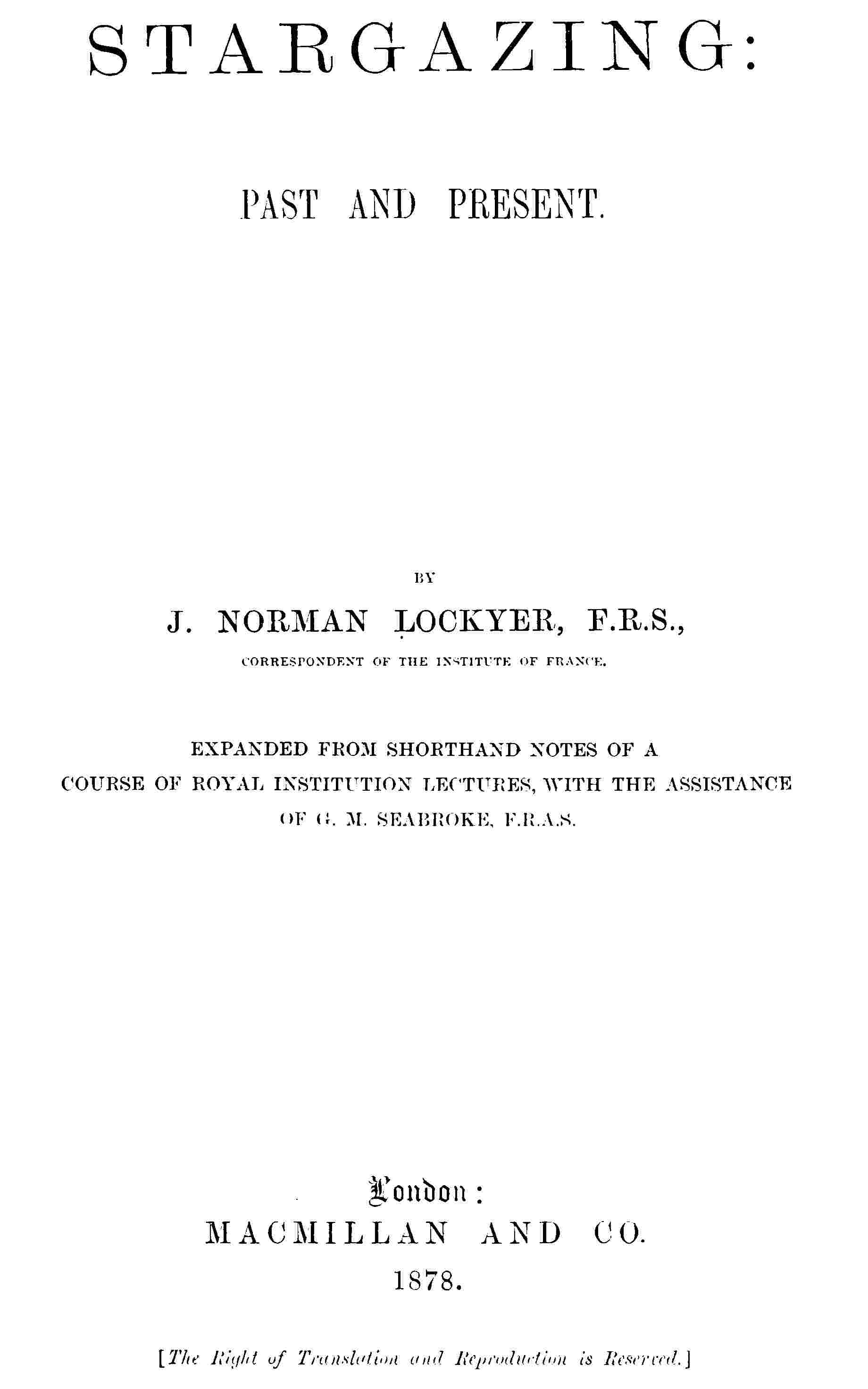
We have now considered the mounting and adjustment of the equatorial, be it reflector or refractor. If of large dimensions it will require a special building to contain it, and this building must be so constructed that, as in the case of the Melbourne and Paris instruments, it can be wheeled away bodily to the north, leaving the instrument out in the open; or the roof must be so arranged that the telescope can point through an aperture in it when moved to any position. This requirement entails (1) the removal of the roof altogether, by having it made nearly flat, and sliding it bodily off the Observatory, or (2) the more usual form of a revolving dome, with a slit down one side, or (3) the Observatory maybe drum-shaped, and may run on rollers near the ground. The last form is adopted for reflectors whose axis of motion is low; but with refractors having their declination axis over six or seven feet from the ground, the walls of the Observatory can be fixed, as the telescope, when horizontal, points over the top. The roof, which may be made of sheet-iron or of wood well braced together to prevent it altering in shape, is built up on a strong ring which runs on wheels placed a few feet apart round the circular wall, or, instead of wheels, cannon balls may be used, rolling in a groove with a corresponding groove resting on them. A small roof, if carefully made, may be pulled round by a rope attached to any part of it, but large ones generally have a toothed circle inside the one on which the roof is built, or this circle itself is toothed, so that a pinion and hand-winch can gear into it and wind it round. If the roof is conical in shape the aperture on one side can be covered by two glazed doors, opening back like folding-doors; but if it is dome-shaped, the shutter is made like a Venetian blind or revolving shop-window shutter, and slides in grooves on either side of the opening.
Fig. 151.—Dome.
Fig. 152.—Drum.
Fig. 153.—New Cincinnati Observatory—Front elevation, showing exterior of Drum.
Fig. 154.—Cambridge (U.S.) Equatorial, showing Observing Chair and rails.
The equatorial and the building to contain it have now been described, but there is another piece of apparatus which is required as much as any adjunct to the equatorial, and that is the chair or rest for the observer. Since the telescope may be sometimes horizontal, and at other times vertical, the observer must be at one time in an upright position, and at another lying down and looking straight up. A rest is required which will carry the observer in these or in intermediate positions. A convenient form of rest for small telescopes consists of a seat like that of a chair, with a support moving on hinges at the back of the seat; a rack motion fixes this at any inclination, so that the observer’s back can be sustained in any position, between upright and nearly horizontal. The seat with its back slides on two straight bars of wood, sloping upwards from near the ground at an angle of about 30°, and about 8ft. long; these are supported at their upper ends by uprights of wood, and at their lower ends in the same manner by shorter pieces. These four uprights are firmly braced together, and have castors at the bottom. A rack is cut on one of the inclined slides, and a catch falls into it, so as to fix the seat at any height to which it is placed.
In larger observatories a more elaborate arrangement is adopted, the rails, on which the seat moves, are curved to form part of a circle, having the centre of motion of the telescope for its centre; as the seat with its back is moved up or down on the curved slides, its inclination is changed, so that the observer is always in a favourable position for observing. The seat on its frame runs on circular rails round the pier of the telescope, so that the eyepiece can be followed round as the telescope moves in following a star. A winch by the side of the observer, acting on teeth on one of the rails, enables him to move the chair along, and a similar arrangement enables him to raise or lower the seat on the slides without removing from his place. A steady mounting for the telescope, and a comfortable seat for the observer, are the two things without which a telescope is almost useless.
The observing chair is well seen in the engravings of Mr. Newall’s and the Cambridge telescopes. The eyepieces and micrometer can be carried on the rest, close to the observer, when much trouble is saved in moving about for things in the dark; and for the same reason there should be a place for everything in the observatory, and everything in its place.
Fig. 155.—Section of Main Building—United States Naval Observatory, showing support of Equatorial.
The very high magnifying power employed upon equatorials in the finest states of the air necessitates a very firm foundation for the central pillar. The best position for such an instrument is on the ground, but it is almost always necessary to make them high in order to be able to sweep the whole horizon. The accompanying woodcut will give an idea of the precautions that have to be taken under these circumstances. A solid pillar must be carried up from a concrete foundation, and there must be no contact between this and the walls or floors of the building, when the dome thus occupies the centre of the observatory. The other rooms, generally built adjoining the equatorial room, radiate from the dome, east and west, not sufficiently high to interfere with the outlook of the equatorial. In one of these the transit is placed; an opening is made in the walls and roof, so that it has an unimpeded view when swung from north through the zenith to south, and this is closed when the instrument is not in use by shutters similar to those of the dome.
CHAPTER XXIII.
THE SIDEROSTAT.
At one of the very earliest meetings of the Royal Society, the difficulties of mounting the long focus lenses of Huyghens being under discussion, Hooke pointed out that all difficulties would be done away with if instead of giving movement to the huge telescope itself, a plane mirror were made to move in front of it. This idea has taken two centuries to bear fruit, and now all acknowledge its excellence.
One of the most recent additions to astronomical tools is the Siderostat, the name given to the instrument suggested by Hooke. By its means we can make the sun or stars remain virtually fixed in a horizontal telescope fixed in the plane of the meridian to the south of the instrument, instead of requiring the usual ponderous mounting for keeping a star in the field of view.
It consists of a mirror driven by clockwork so as to continually reflect the beam of light coming from a star, or other celestial object, in the same direction; the principle consisting in so moving the mirror that its normal shall always bisect the angle subtended at the mirror by the object and the telescope or other apparatus on which the object is reflected.
Fig. 156.—Foucault’s Siderostat.
It was Foucault who, towards the end of his life, thought of the immense use of an instrument of this kind as a substitute for the motion of equatorials; he, however, unfortunately did not live to see his ideas realized, but the Commission for the purpose of carrying out the publication of the works of Foucault directed Mr. Eichens to construct a siderostat, and this one was presented to the Academy of Science on December 13th, 1869, and is now at the Paris Observatory. Since that date others have been produced, and they have every chance of coming largely into use, especially in physical astronomy. Fig. 156 shows the elevation of the instrument, the mirror of which, in the case of the instrument at Paris, is thirty centimetres in diameter, and is supported by a horizontal axis upon two uprights, which are capable of revolving freely upon their base. The back of the mounting of the mirror has an extension in the form of a rod at right angles to it, by which it is connected with the clock, which moves the mirror through the medium of a fork jointed at the bottom of the polar axis.
The length of the fork is exactly equal to the distance from the horizontal axis of the mirror to the axis of the joint of the fork to the polar axis, and the direction of the line joining these two points is the direction in which the reflected ray is required to proceed. The fork is moved on its joint to such a position that its axis points to the object to be viewed, and, being carried by a polar axis, it remains pointing to that object as long as the clock drives it, in the same manner as a telescope would do on the same mounting. Then, since the distance from the axis of the mirror to the joint of the fork is equal to the distance from the latter point to the axis of its joint to the sliding tube on the directing rod, an isosceles triangle is formed having the directing rod at its base; the angles at the base are therefore equal to each other.
Further, if we imagine a line drawn in continuation of the axis of the fork towards the object, then the angle made by this line and that from the axis of the mirror to the elbow joint of the fork (the direction of the reflected ray) will be equal to the two angles at the base of the isosceles triangle; and, since they are equal to each other, the angle made by the directing rod and the axis of the fork (or the incident ray) from the object, is equal to half the angle made by the latter ray and the direction of the reflected ray; and if lines are drawn through the surface of the mirror in continuation of the directing rod and the line from the elbow joint to the axis of the mirror; and a line to the point of intersection be drawn from the object, this last line will be parallel to the axis of the fork, and the angle it makes with the continuation of the directing rod, or normal to the surface of the mirror, will be half the angle made by it and the line representing the reflected ray. Therefore the angle made by the incident ray and the required direction of the reflected ray is always bisected by the normal, so that the reflected ray is constant in the required direction.
The clock is driven in the usual manner by a weight. A rod carries the motion up to the system of wheels by which the polar axis is rotated. As this axis rotates it carries with it the fork, which transmits the required motion to the mirror. And as the fork alters its direction the tube slides upon the directing rod, thus altering the inclination of the mirror. In order to vary the position of the mirror without stopping the instrument there are slow motion rods or cords proceeding from the instrument which may be carried to any distance desirable.
Fig. 157.—The Siderostat at Lord Lindsay’s Observatory.
The polar axis is set in the meridian similarly to an equatorial telescope, the whole apparatus being firmly mounted upon a massive stone pillar which is set several feet in the ground, and rests upon a bed of concrete, if the soil is light. A house upon wheels, running upon a tramway, is used to protect the instrument from the weather, and when in use this hut is run back to the north, leaving the siderostat exposed. In the north wall of the observatory is a window, and the telescope is mounted horizontally opposite to it: so the observer can seat himself comfortably at his work, and by his guide rods direct the mirror of the siderostat to almost any part of the sky, viewing any object in the eyepiece of his telescope without altering his position. In spectroscopy and celestial photography its use is of immense importance, for in these researches the image of an object is required to be kept steadily on the slit of the spectroscope or on the photographic plate, and for this purpose a very strongly-made and accurate clock is required to drive the telescope and mounting, which are necessarily made heavy and massive to prevent flexure and vibration. The siderostat, on the other hand, is extremely light, without tube or accessories, and a light, delicate clock is able to drive it with accuracy, while the heavy telescope and its adjuncts are at rest in one position. The sun and stars can, therefore, as it were, be “laid on” to the observer’s study to be viewed without the shifting of the observatory roof and equatorial, or of the observing chair, which brings its occupant sometimes into most uneasy positions.
We figure to ourselves the future of the physical observatory in the shape of an ordinary room with siderostat outside throwing sunlight or rays from whatever object we wash into any fixed instrument at the pleasure of the observer. There are, however, inconveniences attending its use in some cases; for instance, in measuring the position of double stars, the diurnal motion gradually changes their position in the field of the telescope, so that a new zero must be constantly taken or else the time of observation noted and the necessary corrections made.
CHAPTER XXIV.
THE ORDINARY WORK OF THE EQUATORIAL.
The equatorial enables us to make not only physical observations, but differential observations of the most absolute accuracy.
First we may touch upon the physical observations made with the eyepiece alone—star-gazing, in fact. The Sun first claims our attention: our dependence on him for the light of day, for heat, and for in fact almost everything we enjoy, urges us to inquire into the physics of this magnificent object. Precautions must however be taken; more than one observer has already been blinded by the intense light and heat, and some solar eyepiece must be used. For small telescopes up to two inches, a dark glass placed between the eye and the eyepiece is sufficiently safe; for larger apertures, the diagonal reflector, or Dawes’ solar eyepiece, already described, comes into requisition. Another method of viewing the sun is to focus the sun’s image with the ordinary eyepiece on a sheet of paper or card, or, better still, on a surface of plaster of Paris carefully smoothed. The bright ridges or streaks, usually seen in spotted regions near the edge, called the faculæ, and the mottled surface, appearing, according to Nasmyth, like a number of interlacing willow-leaves—the minute “granules” of Dawes, are best seen with a blue glass; but for observing the delicately-tinted veils in the umbræ of the spots a glass of neutral tint should be used.
The Moon is a fine object even in small telescopes. The best observing time is near the quarters, as near full moon the sun shines on the surface so nearly in the same direction as that in which we look, that there is no light and shade to throw objects into view. Hours may be spent in examining the craters, rilles, and valleys on the surface, accompanied with a good descriptive map or such a book as that which Mr. Neison has recently published.
The planets also come in for their share of examination. Mercury is so near the sun as seldom to be seen. Venus in small telescopes is only interesting with reference to her changes, like the moon, but in larger ones with great care the spots are visible. Mars is interesting as being so near a counterpart of our own planet. On it we see the polar snows, continents and seas, partially obscured by clouds, and these appearances are brought under our view in succession by the rotation of the planet. With a good six-inch glass and a power of 200 when the air is pure and the opposition is favourable, there is no difficulty in making out the coast-lines, and the various tones of shade on the water surface may be observed, showing that here the sea is tranquil, and there it is driven by storms. Up to very lately it was the only planet of considerable size further off the sun than Venus that was supposed to have no satellite; two of these bodies have however been lately discovered by Hall with the large Washington refractor of twenty-six inches diameter, and they appear to be the tiniest celestial bodies known, one of them in all probability not exceeding 10 miles in diameter. Jupiter and Saturn are very conspicuous objects, and the eclipses, transits, and occultations of the moons, and the belts of the former and rings of the latter, are among the most interesting phenomena revealed to us by our telescopes, while the delicate markings on the third satellite of Jupiter furnish us with one of the most difficult tests of definition. Uranus and Neptune are only just seen in small telescopes, and even in spite of the use of larger ones, we are in ignorance of much relating to these planets. The amateur will do well to attack all these with that charming book, the Rev. T. W. Webb’s Celestial Objects for Common Telescopes, in his hand.
To observe the fainter satellites of the brighter planets, or, indeed, faint objects generally, near very bright ones, the bright object may be screened by a metallic bar, or red or blue glass placed in the common focus.
So much with regard to our own system. When we leave it we are confounded with the wealth of nebulæ, star-clusters, and single or multiple systems of stars, which await our scrutiny. With the stars, not much can be done without further assistance than the eyepiece alone. The colours of stars may however be observed, and for this purpose a chromatic scale has been proposed, and a memoir thereon written, by Admiral Smyth, for comparison with the stars. The colour of a star must not be confused with the colours—often very vivid—produced by scintillations, these rapid changes of brightness and colour depending on atmospheric causes. Of the large stars, Sirius, Vega and Regulus are white, while Aldebaran and Betelgueux are red. In many double and multiple stars however the contrast of colours shows up beautifully; in β Cygni for instance we have a yellow and blue star, in γ Leonis, a yellow and a green star; and of such there are numerous examples.
Interesting as all these observations are, a new life and utility are thrown into them when instead of using a simple eyepiece the wire micrometer is introduced. This, as we have before stated, generally consists of one wire, or two parallel wires, fixed, and one or two other wires at right angles to these, movable across the field. This micrometer is used in connection with a part of the eyepiece end of the telescope, which has now to be described. This is a circle, the fineness of the graduation of which increases with the size of the telescope, read by two or four verniers. The circle is fixed to the telescope, while the verniers are attached to the eyepiece, carrying the micrometer, which is rotated by a rack and pinion.
The whole system of position circle (as it is called) and wire micrometer, is in adjustment when (1) the single or double fixed wires and the movable ones cross in the centre of the field, and (2) when with a star travelling along the single fixed or between the two fixed wires, the upper vernier reads 180 and the lower one reads zero.
This motion across the field gives the direction of a parallel of declination; that is to say, it gives a line parallel to the celestial equator, and, knowing that, one will be able at once, by allowing the object to pass through the field of view, to get this datum line. For instance, supposing the whole instrument is turned round on the end of the telescope, so that one of the two wires x and y, Fig. 104, at right angles to the thin wires for measuring distance, shall lie on a star during all its motion across the field of view; then those two wires, being parallel to the star’s motion, will represent two parallels of declination; and we use the direction of the parallels of declination to determine the datum point at right angles to them, that is, the north point of the field. We have then a position micrometer, that is, one in which the field of view is divided into four quadrants, called north preceding, north following, south preceding, and south following, because if there be an object at the central point it will be preceded and followed by those in the various quadrants. The movable wires lie on meridians and the fixed ones on parallels when adjusted as above.
Fig. 158.—Position Circle.
The position circle is often attached to, and forms part of, the micrometer instead of being fixed to the telescope, and in screwing it on from time to time, the adjustment of the zero changes, and the index error must be found each time the micrometer is put on the telescope.
In practice it is usual to take the north and south line as the datum line, and positions are always expressed in degrees from the north round by east 90°, south 180°, and west 270°, to north again in the direction contrary to that of the hands of a clock.
The angle from the east and west line being found by the micrometer, 90° is either added or subtracted, to give the angular measurement from north. But to make these measurements we want a clock; a clock which, when we have got one of these objects in the middle of the field of view, shall keep it there, and enable the telescope to keep any object that we may wish to observe fixed absolutely in the field of view. But in the case of faint objects this is not enough. We want not only to see the object, but also the wires we have referred to. Now then the illuminating-lamp and bright wires, if necessary, come into use.
The following, Fig. 159, will show how we proceed if we merely wish to measure a distance, the value of the divisions of the micrometer screw having been previously determined by allowing an equatorial star to transit. It represents the position of the central and the movable wire when the shadow thrown by the central hill of the the lunar crater Copernicus is being measured to determine the height of the hill above the floor of the crater. It has been necessary to let the fixed wire lie along the shadow; this has been done by turning the micrometer; but there is no occasion to read the vernier.