CHAPTER XII.
“Brougham,” Stockton and Darlington Railway—L. & N.W.R. engines at the 1862 Exhibition—Sinclair’s “Single” engines for the G.E.R.—French locomotives on the G.E.R.—L. & S.W.R. tank engines, afterward converted to tender engines—Conner’s 8ft. 2in. “Single” engine on the Caledonian Railway—The lilliputian “Tiny,” the Crewe Works locomotive—“Dignity and Impudence”—Bridges Adams’ radial axle tank engines—His springtyres— Account of the St. Helens Railway locomotive with these innovations—Broad-gauge engines for the Metropolitan Railway—Rupture between the Great Western and Metropolitan —Sturrock to the rescue—G.N. tender engines on the Metropolitan—Delivery of the Underground Company’s own engines—Great Northern “condensing” locomotives—The Bissell bogie truck well advertised—End of the “hot-brick” engine—Sturrock’s steam-tender engines on the G.N.R.—Sinclair’s tank engine with Bissell trucks—Fell’s system of locomotive traction—Tried on the Cromford and High Peak line—Adopted on the Mount Cenis Railway—Spooner’s locomotives for the Festiniog Railway—Fairlie’s double-bogie engines—The “Welsh Pony” and “Little Wonder”—Fairlie’s combined trains and engines—Cudworth’s trailing bogie North London engines, a model for tank locomotive constructors—Pryce’s designs for the North London Railway.
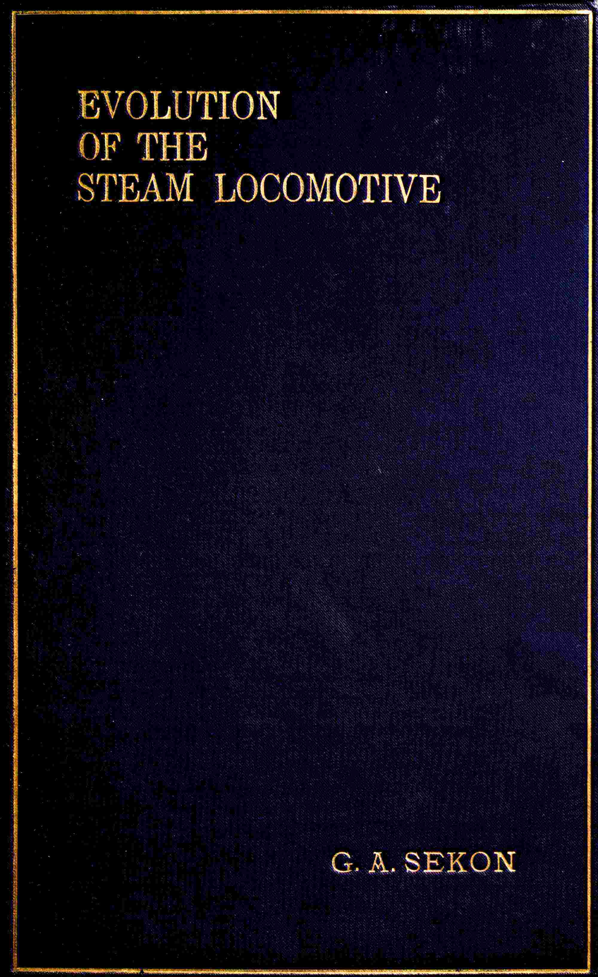
Fig. 82 illustrates the “Brougham,” No. 160, of the Stockton and Darlington Railway. This engine was designed for hauling passenger trains. She was a bogie engine, as will be noticed by reference to the illustration, and had four-coupled wheels 6ft. in diameter. The cylinders, placed outside, were 16in. in diameter, with a stroke of 24in. The tender was on six wheels, and the tank was capable of carrying 1,400 gallons. No. 160 was constructed in 1860, not a very long time prior to the amalgamation with the North Eastern Railway Company, by R. Stephenson and Co., of Newcastle, at a cost of £2,500.
The London and North Western Railway exhibited at the London International Exhibition of 1862 a locomotive constructed at Wolverton from the designs of Mr. McConnell; the engine was built the previous year, was numbered 373, and named “Caithness.” The cylinders were 18in. by 24in.; driving wheels, 7ft. 7⅛in. diameter; L. and T., 4ft. 7½in.; steam pressure, 150lb.; wheel base, 18ft.; heating surface (14 tubes 1⅞in. diameter, 9ft. 4in. long), 980.319 sq. ft.; fire-box, 242.339 sq. ft.; weight in working order (engine and tender) 59 tons 14 cwt. A combustion chamber 2ft. 8in. long was provided. Two other engines of this design were built, No. 372 “Delamere” and No. 272 “Maberley.” Apparently these engines were not very successful, as we do not find accounts of their later performances.
In 1862 Fairbairn and Co. constructed for the Great Eastern Railway a class of “single” engines designed by Mr. R. Sinclair. These locomotives had outside cylinders, 16 ft. by 24 in.; driving wheels, 7 ft. 3 in., and leading and trailing wheels, 3 ft. 9 in. diameter; heating surface, tubes (203, 1¾ in. diameter), 957.6 sq. ft.; fire-box, 94.9 sq. ft.; grate area, 15.27 sq. ft.; weight, 32 tons, of which 13 tons 13 cwt. 1 qr. was on the driving axle. Gooch’s link motion was employed.
Fig. 82.—“BROUGHAM,” No. 160, STOCKTON AND DARLINGTON RAILWAY
The design in question was of rather attractive appearance, the open splasher being an attractive feature, as was also the cab—somewhat of an innovation 35 years ago. Mr. S. W. Johnson succeeded Mr. Sinclair at the end of 1865 as Great Eastern Railway locomotive superintendent, and under the régime of the former some of these engines were rebuilt with a leading bogie, and the diameter of the cylinders was increased to 18 in. Another form of cab was introduced, the Salter safety valve on the dome was removed, and one of Ramsbottom design placed on the flush top fire-box, which had superseded the raised pattern as employed in this class of engine by Mr. Sinclair. One of the engines of this class (No. 0295) was in active service as recently as July, 1894. In connection with this class of engine a special circumstance needs mention—viz., that 16 of these locomotives were made—not “in Germany,” but in the country of her foe; the French engineering firm with the German name of Schneider, in 1865, contracting to supply the 16 locomotives at a less price than any English maker. This event was certainly a curiosity in the economic history of this country’s trade. We import many articles; let us hope, however, that foreign locomotives will not again be seen on English railways. There is some consolation to be found in the statement that all the British locomotive builders were so full of orders at the time that they practically refused to accept orders for the engines in question by tendering for them at outside prices, so that consequently the order had to be given to a foreign firm.
In 1863 Beyer, Peacock and Co. commenced to construct a class of tank engines for the London and South Western Railway from the designs of Mr. J. Beattie. The locomotives in question had outside cylinders 16½in. by 20in. stroke; four coupled wheels, 5ft. 7in. diameter; and a pair of leading wheels, 3ft. 7¾in. diameter. The boiler contained 186 tubes, 1⅝in. diameter. The heating surface was made up of tubes 715.17 sq. ft., and fire-box 80 sq. ft. The grate area was 14.2 sq. ft.
A lock-up safety valve was placed on the front ring of the boiler barrel, and two of Salter’s pattern on the immense dome which surmounted the raised fire-box. The steam pressure was 130lb. The engine weighed in working order 29 tons 17 cwt., of which 10½ tons was on the driving axle. We have already stated that the engines were built as tanks, but Mr. W. Adams, who had succeeded Mr. J. Beattie as locomotive superintendent of the London and South Western Railway, added tenders to some of their engines in 1883. It is a common practice to rebuild tender engines as “tanks,” but the opposite practice is somewhat of a novelty. The tenders were supported on six wheels, 3ft. 9¾in. diameter, and weighed 20¾ tons in working order, the water capacity being 1,950 gallons.
An engine that attracted considerable attention at the 1862 Exhibition was one built by Neilson and Co. from the designs of Mr. B. Conner, locomotive superintendent of the Caledonian Railway (Fig. 83). The engine in question had outside cylinders, 17¼in. diameter, with a stroke of 24in.; driving 8ft. 2in. in diameter, with inside bearings and underhung springs. The trailing and leading wheels had outside bearings. The engine had 1,172 sq. ft. of heating surface; the grate area was 13.9 sq. ft.; wheel base, 15ft. 8in.; weight, empty, 27¼ tons; in working order, 30 tons 13 cwt., of which 14 tons 11 cwt. was on the driving axle.
Fig. 83.—CONNER’S 8ft. 2in. “SINGLE” ENGINE, CALEDONIAN RAILWAY (REBUILT)
Colburn describes the locomotive as a “fine, well-constructed engine, standing gracefully on its wheels, large, yet compact, and qualified to run at any speed with ease and steadiness.” Nor can this description be in any measure contradicted. For, until Stirling built his famous 8ft. 1in. “singles” for the Great Northern Railway, Conner’s 8ft. 2in. Caledonian engines were far and away the most graceful locomotives ever placed on the 4ft. 8½in. gauge. In general design, the engine was a modification of the old Crewe pattern engine. The dome was, however, of rather a peculiar shape: it was placed on the top of the raised fire-box. The driving axle was of cast steel, and the tyres of Krupp steel. The large number of spokes in the driving wheels was noticeable, being at only 10in. centres at the rim of the wheels. The slide-valves were provided with 1½in. lap. A great improvement was the provision of a cab, and that of not disproportionate dimensions, considering the “year of grace” in which the engine was constructed. Trains of nine carriages were hauled at an average speed of 40 miles an hour, with a coal consumption of 2½lb. per mile; 14 loaded carriages were frequently taken up the terrible Beattock bank, 10 miles in length, at 30 miles an hour.
The late Khedive of Egypt was so taken with the appearance of this engine when it was at the Exhibition that he immediately ordered one for his own railway. He was searching for a locomotive to convey him at 70 miles an hour, and Conner’s 8ft. 2in. single appeared to be the one most likely to fulfil his requirements. Nor do we hear that he was in any way disappointed with his purchase.
It is interesting to know that the Caledonian Railway has still a specimen of this notable design unscrapped—may it ever remain so. To prevent our appetite becoming vitiated with a galaxy of Brobdingnagian locomotives, we will descend to the other end of the scale, and detail the Lilliputian “Tiny,” as used in the Crewe locomotive works. The railway is of 18in. gauge, and was opened in May, 1862, for a length of three-eighths of a mile. In its course the engine traverses curves of 15ft. radius each, no difficulty being found in going round these curves with loads of 12 to 15 tons, or in taking 7ft. 6in. wheel forgings or tyres on edge by means of trucks specially adapted for the purpose. This engine has four-wheels-coupled; inside cylinders, 4¼in. diameter, and 6in. stroke; the wheels are 15in. in diameter, on a base of 3ft. The total heating surface is about 42 sq. ft. A No. 2 Giffard’s injector supplied the boiler with water; this precious liquid is stored in a saddle tank, with a capacity of 28 gallons. “Tiny,” when “right and tight and ready for action,” weighs only 2½ tons.
The duties of the Lilliputian engines consist in hauling materials to and from different parts of the works, and as the 18in. rails are in most places laid parallel with the standard gauge lines, “Tiny” is also called upon to fly shunt the trucks, etc., when necessary.
An engine of this type, the “Nipper,” forms with the giant “Cornwall” that well-known photographic picture—the railway “Dignity and Impudence.”
Fig. 84 represents Sharp, Stewart, and Co.’s standard design of passenger engine of this period. The “Albion” was delivered to the Cambrian Railway in May, 1863. She was an inside cylinder engine, with a pair of leading wheels, and an enclosed Salter safety valve. Altogether, the “Albion” is a fair example of locomotive practice 36 years ago.
We have on previous occasions referred to the improvements in locomotive construction introduced by Mr. W. Bridges Adams, and we now have again to record a successful employment of his design. In the first week of November, 1863, Mr. James Cross, locomotive engineer of the St. Helens Railway, completed a tank locomotive, supported on eight wheels, the leading and trailing pairs of which were fitted with the radial axle-boxes patented by Mr. W. B. Adams; whilst the four coupled wheels were fitted with spring tyres, which were another invention of the same engineer.
Fig. 84.—“ALBION,” CAMBRIAN RAILWAYS, 1863
The St. Helens Railway was famous—or, from an engineer’s point of view, we should say, perhaps, infamous—for the severe gradients, sharp curves, and numerous points, crossings, and junctions. The inclines were as steep as 1 in 35, 1 in 70, and 1 in 85, whilst the curves were constructed with radii of 300ft. and 500ft., and reverse or S curves were also more frequent than pleasant. The St. Helens Railway was only 30 miles long, but within two miles of the St. Helens Station no less than 12 miles of sidings were located. We do not mean to suggest that the whole line of railway was so thickly covered with siding connections, but such were distributed over the remaining mileage of the railway in too plentiful profusion. Here, then, was a length of railway containing the three great hindrances to smooth and quick running, but the locomotive about to be described was so constructed as to successfully overcome these impediments.
This engine had inside cylinders, 15in. diameter and 20in. stroke. The coupled wheels were 5ft. 1in. in diameter, the rigid wheel base being 8ft., but as these wheels had spring tyres, each pair of wheels was practically as free to traverse the curves as uncoupled wheels. Other dimensions were:—Heating surface, 687 sq. ft.; grate area, 16.25 sq. ft.; total wheel base, 22ft.; weight in working order, on leading wheels, 7 tons 15 cwt.; on driving, 11¾ tons; on rear coupled, 11¼ tons; on trailing, 10 tons, including 4¼ tons water and 1¼ tons coal. Total weight, 40¾ tons.
The boiler contained 121 tubes, 10ft. 11in. long, and 1⅞in. diameter; steam pressure, 140lb.; water capacity of tank, 950 gallons. The fire-grate was 5ft. long, and sloped from the door to the tube-plate. The springs of the coupled wheels were connected by means of a compensation lever. The dome was placed on the raised fire-box, and fitted with a screw-down safety valve; a second valve of the same pattern was fixed on the boiler barrel. A roomy and well-enclosed cab, fitted with side windows, thoroughly protected the enginemen.
Adams’ radial axle-boxes are, of course, still in use on the Great Northern Railway, London, Chatham, and Dover Railway, and other lines, so that a detailed account here is not necessary, the salient feature being that they are made with a radius, having its centre in the centre of the adjoining axle, the axle-box guide-boxes being curved to fit. In the engine we are now describing the radius of the boxes was 7ft., and the lateral play of the boxes was 4½in. on each side. The spring-pins were not fixed on the top of the boxes, but were each fitted with a small roller to allow the boxes to freely traverse. The axle-boxes weighed 3½ cwt. each.
It will be understood that when an engine fitted with these boxes enters a right-hand curve the flanges of the leading wheels draw the boxes to the right, so that the engine itself remains a tangent to the curve, whilst, since the axle-boxes are themselves curved, the effect is that the right-hand side axles are brought nearer the rigid wheels, and consequently the radial wheels on the opposite side of the engine further from the fixed wheels, the whole effect of the radial axle-boxes being that the trailing and leading axles actually become radii of the curves being traversed, although the flanges continue parallel to the rails.
Adams’ spring tyres require a more precise description, and before we describe them, readers may perhaps be reminded that Adams had strong views on the subject of railway rolling stock wheels. He enters rather fully into the matter in his book, “Roads and Rails,” especially in the chapter dealing with “the mechanical causes of accidents.” In this, Adams maintains that the usual forms of wheels are in reality rollers, and not wheels.
The spring tyres had been tried on the North London Railway, Eastern Counties, and on another locomotive on the St. Helens Railway, before the engine now under review was constructed. Upon the coupled wheels of the new locomotive for the latter railway, double spring hoops were employed, the single form having been used in the three previously mentioned engines. The plan adopted was as follows:—
“The tyres chosen were constructed with a deep rib in front; this was bored out, internally, to a depth of ¾in., and to a conical section, and, of course, parallel to the tread. A flat edge, ⅜in. wide, was thus left on either side.
“The springs, formed of tempered hoop steel, were placed on the inner surface of the tyres. Corresponding curves were turned across the outer circumference of the wheels. The wheels were forced into the cones containing the springs, and retained by three 1in. bolts, and a flat ring in the groove at the back of the tyre, the effort of the spring tyres being to allow of a slight lateral motion in running round curves and also to give a better grip of the rails, as the tyres, by reason of the weight upon them being transmitted through the tyre springs, slightly flattened upon the rails, and so presented a larger surface for adhesion between the tyres and rails.”
The following interesting account of the working of the radial axle and spring tyre locomotive on the St. Helens Railway is extracted from a paper by Mr. J. Cross, the designer of the locomotive, and read before the Institution of Civil Engineers. Mr. Cross stated that “the engine was completed in the first week of November, 1863, and has since been running very regularly, taking its turn of duty with passenger trains or coal trains, or as a shunting engine; and about the numerous works connected by sharp curves with the St. Helens line. The motion round curves is free from all jerking, and on straight lines the speed is more than 60 miles an hour; either end of the engine being first, without any train behind to give steadiness; and the motion is so smooth that it has only been by taking the actual time that the engineers have convinced themselves of the fact of the speed exceeding 40 miles an hour. It was built to traverse curves of 200ft. radius. This it does with the greatest facility, and it has regularly worked the passenger trains round a curve of 1,000ft. radius, going directly off the straight line by a pair of facing points at a speed of more than 30 miles an hour, and it has gone round curves of 132ft. radius. It has also run a train of 12 passenger carriages, weighted up to 100 tons, exclusive of its own weight, at 60 miles an hour on the level. From the advantages it possesses over the ordinary mixed engines for weighting the trailing coupled wheel, it, without difficulty, on a wet, slippery day, started, and took this load up a gradient of 1 in 70, drawing seven of the carriages with a load weighing 72 tons 5 cwt., up a gradient of 1 in 36, round a curve of 440ft. radius; and coal trains of 250 tons are worked over long gradients of 1 in 200 with the greatest ease.
“It is evident, then, that engines on this principle, affording facilities for the use of high power in hilly countries, are peculiarly adapted for Metropolitan lines, where sharp curves are a necessity (being equally safe whichever end is foremost), and are also well suited for light lines in India and the Colonies. It may likewise be remarked that carriages and wagons on this principle would carry heavier freights, with a saving in the proportion of dead weight, while their friction round curves would be less than at present.”
The improvements adopted in the construction of this locomotive for the St. Helens Railway were so successful that, as usual, other claimants, who appropriated the radial axle-boxes as their invention, were soon contending with Adams and Cross as to who was entitled to the honour of introducing the improvement.
The first portion of the Metropolitan Railway was opened on January 18th, 1863, and the line was then worked on the broad-gauge by the Great Western Railway for a percentage of the receipts. The Great Western Railway provided the stations, staff, locomotives, and rolling stock.
Mr. D. Gooch, in 1862, designed a special class of tank engines for working the Metropolitan Railway. They were six-wheel engines, the driving and trailing wheels being 6ft. diameter and coupled. The cylinders were outside. A special form of fire-box and baffle-plate was employed, and tanks were provided beneath the boiler barrel, into which the exhaust steam was discharged by means of a reversing valve fitted to the bottom of the blast pipe. When in the open air, the waste steam escaped up the chimney in the usual manner.
The first of these engines were named: Bee, Hornet, Locust, Gnat, Wasp, Mosquito, Bug, Khan, Kaiser, Mogul, Shah, and Czar. Later ones were named after flowers and Great Western Railway officers.
A dispute arose between the two companies at the beginning of August, 1865, and immediately developed into a complete rupture. The smaller quasi vassal railway, through the energy displayed by its chief officers, successfully overcame the apparently insurmountable obstacles that beset it, and consequently the Metropolitan Railway asserted its complete independence of the Great Western Railway, and has since maintained it.
It was indeed a nine days’ wonder that the Metropolitan Railway was called upon to perform, for it had to obtain from somewhere locomotives and carriages to work the underground line, commencing on the morning of August 10th, 1863.
Mr. Sturrock, the locomotive superintendent of the Great Northern Railway, had at this time under construction a class of condensing-tank engines that he had designed to work the Great Northern Railway traffic over the Metropolitan Railway. The directors of the Metropolitan Railway in this emergency applied to Mr. Sturrock for assistance, and by working day and night he managed to fit up some Great Northern tender engines with a temporary condensing apparatus.
The difficulty was to provide some kind of condensing apparatus on the Great Northern tender engines, it being necessary to use flexible connecting pipes between the engine and tender strong enough to withstand the steam pressure, but Mr. Sturrock was successful enough to contrive the necessary flexible pipes by which the exhaust steam was conveyed from the engine to the water-tank of the tender, but these pipes very frequently burst, and all concerned were far from sorry when the proper engines were delivered.
An order for eighteen had already been placed with a well-known Manchester firm of locomotive builders by the Metropolitan Railway, Beyer, Peacock, and Co. building them from the designs of the late Mr. (afterwards Sir) John Fowler.
The type is well known to London readers, the engines having side tanks, a leading bogie, the wheels of which were 3ft. diameter, with a base of 4ft. The driving and trailing wheels (coupled) were 5ft 9in. diameter, their base being 8ft. 10in.; the total wheel base being 20ft. 9in., or to centre of bogie, 18ft. 9in. The cylinders were outside, slightly inclined from the horizontal, 17in. diameter, and 24in. stroke. The grate area was 19 sq. ft. The fire-boxes had sloping grates, which were 6in. deeper at the front than the back. The boiler barrel was 4ft. in diameter, and 10ft. 3in. long; it contained 166 tubes, 2in. diameter, the total heating surface being 1,014 sq. ft. The working pressure was nominally 130lb. per sq. in., but when working through the tunnels, condensing the steam, and with the dampers closed, a very much lower pressure resulted. The frames were inside, the dome (fitted with a Salter valve) was on the boiler barrel, close to the smoke-box, a sand-box being also fixed on the boiler barrel at the back of the dome.
The bogie truck was built of plate frames, and was on the Bissell system, turning on a centre-pin fixed to the engine frame, at a radial distance of 6ft. 8in. from the centre of the truck. “Locomotive Engineering” says that “this radial length ensures a nearly correct radiality of the bogie to curves of all radii, the proper length of the radius to ensure exact radiality of the centre of the bogie for all curves being 7ft. 2in., or 6in. more than the actual length—a difference which is, perhaps, of no great importance in practice.”
For the purpose of effectually condensing the exhaust steam the side tanks were only filled with water to within 6in. of the top, and the steam was discharged upon the surface of the water, from a 7in. pipe on each side—one to each tank. Into the mouth of these 7in. pipes a 4in. pipe was projected a short distance, and the other end of the 4in. pipe was below the surface of the water, so that a portion of the steam was discharged right into the water in the tanks, and agitated the water sufficiently to prevent the surface of the water from becoming too hot, as would have been the case if the same portion of the water had always been presented to the waste steam. The tanks held 1,000 gallons, and at the end of a journey the water had become too warm to properly condense the exhaust, and it therefore became necessary to quickly empty the tanks and to take in a fresh supply of cold water.
To expeditiously perform the former operation, each tank was provided with a pipe 7in. in diameter; this led to a cast-iron valve-box being placed below the foot-plate. By means of a screw, worked from the foot-plate, a 10in. valve was operated, and the water in the tanks could be discharged into the pits below the engine in the course of some 60 seconds.
The following list gives the names and builders’ numbers of the first locomotives constructed for the Metropolitan Railway:
| Engine No. | Name. | Builder’s No. | Engine No. | Name. | Builder’s No. |
|---|---|---|---|---|---|
| 1 | Jupiter. | 412 | 10 | Cerberus. | 421 |
| 2 | Mars. | 413 | 11 | Lutona. | 422 |
| 3 | Juno. | 414 | 12 | Cyclops. | 423 |
| 4 | Mercury. | 415 | 13 | Daphne. | 424 |
| 5 | Apollo. | 416 | 14 | Dido. | 425 |
| 6 | Medusa. | 417 | 15 | Aurora. | 426 |
| 7 | Orion. | 418 | 16 | Achilles. | 427 |
| 8 | Pluto. | 419 | 17 | Ixion. | 428 |
| 9 | Minerva. | 420 | 18 | Hercules. | 429 |
These engines were fitted with a very small coal bunker, only 18in. wide. Weight of engine in working order: on bogie, 11 tons 3½ cwt.; driving, 15 tons 9½ cwt.; and trailing, 15 tons 10 cwt. Total weight, 42 tons 3 cwt.
Mr. Sturrock’s engines for working the Great Northern trains over the Metropolitan Railway were numbered 241 to 250, their leading dimensions being:—Cylinders (inside), 16½in. diameter, 22in. stroke; leading and driving wheels (coupled), 5ft. 6in.; trailing wheels, 4ft. diameter; wheel base, L. to D., 7ft. 6in.; D. to T., 11ft. 9in.; total, 19ft. 3in. Weight, empty, 32 tons 4 cwt. 1 qr.; in working order, 39 tons 12 cwt. 2 qrs.
These Great Northern Railway locomotives were fitted with Adams’ radial axle-boxes to the trailing wheels, and commenced working at the end of October, 1865.
The patentee of the Bissell bogie truck did not intend to hide the light of his invention under a bushel, for he advertised the improvement in a truly American style. The following advertisement was to be found in the columns of the sober railway newspapers soon after the Metropolitan locomotives were at work:—
“Important to Railway Directors, Engineers, and the Travelling public.
“No more accidents from engines running off the line (see Queen’s letter to Railway Directors copied in the railway papers January 28th, 1866).
“The Bissell bogie, or safety truck, for locomotive engines, so much prized on American and foreign railroads for the great safety and economy it affords on curved roadways, after years of probationary trial in England, has at length been adopted by John Fowler, Esq., C.E., F.G.S., upon all the new engines, eighteen in number, now working on the Metropolitan Railway, and by Robert Sinclair, Esq., C.E., upon twenty new eight-wheeled engines on the Great Eastern Railway, which may be seen daily. The royalty for the use of the Bissell Patents has been reduced to £10 per engine, so that every engine requiring a bogie underframe should be provided with the Bissell safety truck. Apply to——.”
Whilst on the subject of railway advertisements we take the opportunity to record the obituary announcement of the tentative “hot-brick” engine, previously referred to, designed to work on the Metropolitan Railway. It appeared in the railway newspapers during the early months of 1865, and was to the following effect: “Metropolitan Railway. One locomotive engine for sale, either entire or in parts. For particulars apply to the Locomotive Superintendent, Bishop’s Road, Paddington.”
Reference must here be made to Mr. Sturrock’s system of steam tenders, as adopted by him to work the heavy coal and goods trains on the Great Northern Railway. In addition to the usual engine, the pistons of a pair of cylinders, 12in. diameter, with a stroke of 17in. actuated the centre axle of the tender, and the six tender wheels were coupled by outside rods. The tender wheels were 4ft. 6in. diameter. The steam tenders weighed about 35 tons, with water and coal, and of this weight over 13 tons was on the driving wheels. After use in the tender cylinders, the exhaust steam was condensed in the tender tank. Forty-six of these steam tenders were constructed, and some are still running, but as simple tenders, the propelling apparatus having been done away with many years ago. Fig. 85a represents a Great Northern engine fitted with one of Sturrock’s patent steam tenders.
Mr. Robert Sinclair, whilst locomotive superintendent of the Great Eastern Railway, only designed one type of tank engine, and Neilson and Co. constructed the first of this class in 1864. Twenty of the class were built, being originally intended to work the Enfield Town Branch, but in later years these engines were used on the North Woolwich line. The engines (Fig. 86a) were supported by eight wheels, the leading and trailing being 3ft. 7in. diameter, and the driving and back coupled 5ft. 6in. diameter. The cylinders were outside, 15in. diameter, and 22in. stroke. The leading and trailing wheels were fitted with the Bissell truck, referred to in the advertisement just quoted. So that although the whole wheel base was 17ft. 4in., the rigid base—that of the coupled wheels—was only 6ft. The boiler was 13ft. 6in. long, and the water was carried in the tanks beneath the boiler and between the frames. An enclosed cab with front and rear spectacle plates was provided.
Fig. 85a.—A GREAT NORTHERN RAILWAY ENGINE, FITTED WITH ONE OF STURROCK’S PATENT STEAM TENDERS.
This improvement so delighted the Great Eastern Railway drivers that they presented a testimonial to Mr. R. Sinclair in May, 1864, in which they described him as the “inventor” of the weather-board or “cab,” as fitted to locomotives. The tank engines in question weighed 38 tons 6 cwt. 3 qrs., of which weight 20 tons 5 cwt. 2 qrs. was on the coupled wheels.
Fig. 86a.—SINCLAIR’S DESIGN OF TANK ENGINE FOR THE EASTERN COUNTIES RAILWAY
In January, 1863, Mr. J. B. Fell patented a locomotive designed for working over extremely steep gradients. At that time there was a break 47 miles long in the continuity of the iron road communication between France and Italy by the Mount Cenis route. This break has in later years been abolished by the construction and working of the famous Mount Cenis tunnel. Brassey and Co. in 1863 proposed that during the construction of the tunnel a temporary mountain railway worked on Fell’s system should be built over the mountain. An experimental locomotive was, therefore, constructed at the Canada Works, Birkenhead. This engine weighed 14½ tons loaded. The boiler was 2ft. 9in. diameter, and 7ft. 9½in. long, and contained 100 tubes of 1½in. external diameter. The heating surface was 420 sq. ft., and the grate area 6½ sq. ft. The engine had two sets of machinery—one for working the vertical wheels, acting on the ordinary carrying rails, and the other actuated the special horizontal clutch wheels, which were pressed against the centre rail. The outside cylinders which worked the four-coupled vertical wheels, of 2ft. 3in. diameter, were 11¾in. diameter, the stroke being 18in. The horizontal coupled wheels were 16in. diameter, with a base of 19in.; these were driven by inside cylinders 11in. diameter and 10in. stroke. A pressure of 12 tons, actuated by means of a screw apparatus, could be applied to the horizontal wheels.
By permission of the London and North Western Railway, an experimental railway, 800 yards long, was laid down upon the Whalley Bridge Incline of the Cromford and High Peak Railway.
The gauge was 3ft. 7⅝in., and there were 180 yards of straight line on a gradient of 1 in 13.5, and 150 yards of curves, with radii of 2½ and 3½ chains, on a gradient of 1 in 12. The third rail upon this line, to be clipped between the horizontal driving wheels of the engine, was laid on its side, 7½in. above the other rails.
In the course of a series of experiments carried on from September, 1863, to February, 1864, the engine, working up to a pressure of 120lb. to the square inch, never failed, with a maximum load of 30 tons, to take a load of 24 tons up the above inclines and round the curves. The outer cylinders working on the four vertical wheels could only draw up, besides the weight of the engine, a loaded wagon weighing seven tons; while the inside cylinders, acting upon the horizontal wheels, which pressed with 12 tons against the middle rail, enabled the engine to take up 24 tons on the same day and under the same conditions. The inside cylinders alone were able to carry up the engine itself, round the curves, and exhibited the power of taking up altogether 17 tons.
The results of the experiments on the High Peak Railway were considered so satisfactory that the line up Mount Cenis was commenced without delay. The engine was not properly adapted for working the mountain traffic, in consequence of the crowded and complicated nature of the machinery, and also because the feed-oil dropped on to the horizontal wheels and lessened the bite on the centre rail. The weight on the horizontal wheels was increased to 16 tons, and an additional pair of guide wheels acting on the centre rail was provided at the trailing end of the engine, after the High Peak experiments.
The Board of Trade was at that time so far interested in railway matters as to send out Captain Tyler, one of its inspectors, to report on the Mount Cenis Railway. We extract from his report the following account of the working of this engine on the mountain railway:—
“In the course of two days I took six trips with this engine up and down the experimental line, carrying each time a load of 16 tons, in three wagons, including the weight of the wagons, and it performed in the ascent 1,800 metres in 8⅛min., with a loss of 14lb. of steam and of 5⅓in. of water in the gauge-glass, at steam pressure, varying between 92 and 125lb. to the square inch in the boiler, as the average of all those experiments.
“The speed attained was in every case greater than that which it is proposed to run with the same load with the express trains; and the average speed, as above given, was at the rate of 13⅓ kilometres (or 8⅓ English miles) per hour, instead of 12 kilometres (or 7½ English miles) per hour, which is the highest running speed allowed in the programme given to the French Government for this part of the line.
“The weather was fine and calm, and the bearing rails were in first-rate order; but the middle rail, as well as the horizontal wheels, were oily, and, therefore, in a condition very unfavourable for good adhesion.”
A second engine was built on Fell’s system specially for working over the steep Mount Cenis Railway, and in its construction several improvements, suggested by the shortcomings of the first engine, were introduced.
The second engine was built partly of steel, and weighed 13 tons empty, and 16 tons 17 cwt. fully loaded, afterwards increased to 17 tons 2 cwt. The boiler was 8ft. 4½in. long, and 3ft. 2in. in diameter, and contained 158 tubes of 1½in. external diameter. Fire-box and tubes contained altogether 600 superficial feet of heating surface, and there were 10ft. of fire-grate area. There were only two cylinders, with a diameter of 15in. and stroke of 16in., which worked both the four-coupled horizontal and four-coupled vertical wheels, which were all 27in. in diameter. The wheel base of the vertical wheels was 6ft 10in., and that of the horizontal wheels, 2ft. 4in. The maximum pressure in the boiler was 120lb., and the effective pressure on the piston was 75lb. to the square inch.
Besides possessing a greater amount of boiler power, this engine travelled more steadily than No. 1, its machinery was more easily attended to, and the pressure upon its horizontal wheels could be regulated by the engine-driver at pleasure from the foot-plate. This pressure was applied through an iron rod connected by means of right and left-handed screws, with a beam on each side of the middle rail, and these beams acted upon volute springs which pressed the horizontal wheels against that rail.
The pressure employed during the experiments was 2½ tons on each horizontal wheel, or 10 tons altogether; but the pressure actually provided for, and which when necessary was employed, was 6 tons upon each, or 24 tons upon the four horizontal wheels.
The vertical wheels were worked indirectly by piston-rods from the front, and the horizontal wheels directly by piston-rods from the back of the cylinders.
Having already given Captain Tyler’s account of his experiments with the first engine, we cannot do better than reproduce his statement concerning the second of the Fell engines, built for the Mount Cenis Railway.
Captain Tyler stated that with the new engine he “was able to take up 1,800 metres of the experimental line with the same load as before, of 16 tons in three wagons, in 6¼ minutes, or at a speed of 17¾ kilometres per hour, as against 12 kilometres per hour which it is proposed to run with the express trains. The steam pressure in the boiler fell from 112lb. to 102½lb., and 3in. of water were lost in the gauge-glass, the feed having been turned on during the latter period only of this experiment.
“The engine exerted in this instance, omitting the extra resistance from curves, about 177 horse-power; or, adding 10 per cent. for the resistance from curves, 195 horse-power, or more than 12 horse-power to each ton of its own weight, and nearly 60 horse-power in excess of what was required to take the same load up the same gradient and curves at 12 kilometres per hour, as proposed in the programme. I observed on the following day that 40lb. of steam-pressure in the boiler, or one-third of the maximum pressure employed, was sufficient to move the engine alone up a gradient of 1 in 12½; and the friction of carriages or wagons being proportionately much less than that of an engine, the same engine ought, à fortiori, to be able to move a gross load of three times its own weight, or 48 tons, at its greatest working pressure, up the same gradient.”
Having now given some details of locomotives constructed for working on a foreign steep grade railway, it will not be out of place to describe the special forms of engines designed for the Welsh narrow-gauge line, usually called the Festiniog Railway. The line has been open for a great number of years, but up to June, 1863, had only been used for conveying slates from the quarries to the shipping port. Horses were employed to haul the empty trucks up to the quarries, the loaded wagons running down to Portmadoc by gravity.
The average gradient for 12½ miles was 1 in 92, the steepest 1 in 60. The radii of the curves ranged between two and four chains. Unlike the Mount Cenis line just reviewed, the Festiniog Railway was worked with locomotives depending solely on the adhesion of the carrying wheels, no central rail being provided. The gauge was 1ft. 11½in.
The engines were designed by Mr. C. E. Spooner, the engineer of the railway. At first two were constructed, England and Co. being the builders. These miniature iron horses (one was more correctly called the “Welsh Pony”) had two pairs of coupled wheels, with a wheel base of 5ft. The cylinders, which were outside the framing, were 8½in. in diameter, with a length of stroke of 12in., and they were only 6in. above the rails.
The maximum working pressure of the steam was 200lb. to the square inch. Water was carried in tanks surrounding the boilers, and coal in small four-wheel tenders.
The heaviest of these engines weighed 7½ tons in working order, and they cost £900 each. They could take up, at 10 miles an hour, about 50 tons, including the weight of the carriages and trucks, but exclusive of that of the engine and tender. They actually conveyed daily on the up journey an average of 50 tons of goods and 100 passengers, besides parcels. Two hundred and sixty tons of slates were taken down to Portmadoc daily. The engines were well adapted for convenience in starting and in working at slow speeds, but their short wheel base and the weight overhanging the trailing wheels gave them more or less of a jumping motion when running.
Safety guards, similar in form to snow ploughs, were afterwards added in front of the engines, behind the tenders, and under the platforms of the brake-vans, in consequence of their being so near to the rails.
After a few years’ experience of these four-wheel locomotives, the directors of the Festiniog Railway determined to experiment with an engine constructed on Fairlie’s double-bogie system, and the “Little Wonder” was constructed. In February, 1870, several trials were made with this engine, when a train of 72 wagons, of a total length of 648ft., and of a gross weight, including the engine, of 206 tons 2 qrs., was drawn up an incline of 1 in 85 at a speed of five miles an hour, the steam pressure being 200lb. per square inch. The “Welsh Pony’s” best performance in these trials upon the same gradient, but with a pressure of 150lb., consisted in drawing 26 wagons, the gross load of which, with engine, amounted to 73 tons 16 cwt. Tabulated, the result of these trials were as follows:—
| Total resistance. lbs. per ton gross. |
Gravity. lbs. per ton. |
Frictional resistance. lbs. per ton. |
|||
|---|---|---|---|---|---|
| “Little Wonder” | 40 | 26.3 | 13.7 | ||
| “Welsh Pony” | with | 150lbs steam | 51.4 | 26.3 | 25.1 |
| ” | ” | 130lbs steam | 44.5 | 26.3 | 18.21 |
The general arrangements of the “Little Wonder” may be described as follows. The boiler was double, having two fire-boxes united back to back with two distinct barrels and sets of flue-tubes, and consequently a chimney at each end. A bogie was placed under each barrel, and each bogie had two pairs of wheels coupled together, worked independently by a pair of steam-cylinders to each bogie. Thus a total wheel base of 19ft. 1in. in length was covered by the bogies; each bogie had a 5ft. wheel base, and the distance between the centres of the bogies was 14ft. 1in. The four cylinders were 8³/₁₆in. in diameter, and had a stroke of 13in.; the wheels were 2ft. 4in. in diameter. The combined grate area was 11 sq. ft., and the heating surface 730 sq. ft. Fairlie’s system of double engines soon came into repute for working steep gradients, and many very powerful engines were and are still constructed on his system for use on foreign railways. Fairlie, in conjunction with Samuels, adapted his system to a species of combined locomotive and carriage, and, in 1869, one was constructed for working on the London, Chatham, and Dover Railway between Swanley Junction and Sevenoaks. Seven passenger compartments were provided in this vehicle, accommodation comprising seats for 16 first-class and 50 second-class passengers; its total length was 43ft., and weight, empty, 13½ tons. The leading end was supported by the engine bogie, and the trailing end by an ordinary bogie truck. Curves of only 50ft. radius were easily passed over by the combination vehicle.
Leaving Fairlie and his combinations, both of locomotives and carriages, and also of double locomotives, we now glance at a class of tank engines designed by Cudworth for working the trains between Cannon Street and Charing Cross upon the opening of the former terminus in 1866. These engines were seven in number, and were constructed at the Canada Works. They were of the “coupled in front” pattern, with a trailing bogie. The cylinders were inside, 15in. diameter and 20in. stroke. The coupled wheels were 5ft. 6in. diameter. Outside frames were employed, and also compensation beams both to the coupled and bogie wheels. The coal bunker, with water-tank under, was of exceptional length. It was always a puzzle to the writer as to how a stout driver could manage to squeeze through the narrow entrances to the foot-plate, especially as these apertures were situate at the side of the fire-box; but evidently the “trick was done” by following the axiom, “Where there’s a will there’s a way,” and doubtless the drivers, if asked, would have replied, “It’s very easy if you only know the way.” These South Eastern Railway locomotives were numbered 235 to 241.
Mr. Wm. Gowan, locomotive superintendent of the Great North of Scotland Railway, designed a class of engine, which Neilson and Co. constructed. The design was stated to be that of a “goods” locomotive, but upon examination we find the engines in question to be no other than the popular four-coupled behind, with a leading bogie and outside cylinders. The latter were arranged in a horizontal position immediately below the frames. The coupled wheels were 5ft. 6½in. diameter, with underhung springs connected by means of an equalising lever-beam. The bogie wheels were 3ft. in diameter, with a base of 6ft. Inside bearings were supplied to the bogie axles. The boiler barrel measured 10ft. 10⅛in. between the tube-plates, its external diameter was 4ft. 1in., and it contained 206 tubes of 1¾in. diameter. The engine was fitted with D. K. Clarke’s system of smoke-consuming apparatus, previously described. The fire-box was of the raised pattern, and the steam dome was placed on it. The engine weighed 39 tons 13 cwt., and the tender 27 tons, in working order.
In general appearance this “goods” engine resembled in a remarkable degree the London and South Western Railway express passenger engines as built by Mr. Adams. The tender was carried on six wheels.
Fig. 85b represents Beattie’s standard design of goods engine for the L. and S.W.R. in 1866, the wheels were 5ft. 1in. diameter, the cylinders being inside, and having a diameter of 17in., the stroke 24in. Beyer, Peacock and Co. were the builders. Fig. 86b represents an engine of this class as rebuilt some years later at Nine Elms Works.
In 1868 Mr. W. Adams placed upon the North London Railway the first locomotive constructed from a design which has, in its broad features and general outline, ever since been a model of simplicity, attractiveness, and utility, showing, as the design does, what engines constructed to work important local traffic should be like.