By H. G. PROUT.
The Possibilities of Destruction in the Great Speed of a Locomotive—The Energy of
Four Hundred Tons Moving at Seventy-five Miles an Hour—A Look ahead from a
Locomotive at Night—Passengers Killed and Injured in One Year—Good Discipline
the Great Source of Safety—The Part Played by Mechanical Appliances—Hand-brakes
on Old Cars—How the Air brake Works—The Electric Brake—Improvements
yet to be Made—Engine Driver Brakes—Two Classes of Signals: those
which Protect Points of Danger, and those which Keep an Interval between Trains
on the Same Track—The Semaphore—Interlocking Signals and Switches—Electric
Annunciators to Indicate the Movements—The Block Signal System—Protection for
Crossings—Gates and Gongs—How Derailment is Guarded Against—Safety Bolts—Automatic
Couplers—The Vestibule as a Safety Appliance—Car Heating and
Lighting.
In 1829, when Ericsson's little locomotive "Novelty,"
weighing two and a half tons, ran a short
distance at the rate of thirty miles an hour, a
writer of the time said that "it was the most
wonderful exhibition of human daring and human
skill that the world had ever seen." To-day
trains weighing four hundred tons thunder by at
seventy-five miles an hour, and we hardly note
their passage. We take their safety as a matter of course, and seldom
think of the tremendous possibilities of destruction stored up
in them. But seventy-five miles an hour is one hundred and ten feet
a second, and the energy of four hundred tons moving at that rate
is nearly twice as great as that of a 2,000-pound shot fired from a
100-ton Armstrong gun. This is the extreme of weight and speed
now reached in passenger service, and, indeed, is very rarely attained,
and then but for short distances; but sixty miles is a common
speed, and a rate of forty or fifty miles is attained daily on
almost every railroad in the country. We cannot tell from the
time-tables how fast we travel. The schedule times do not indicate
the delays that must be made up by spurts between stations.
The traveller who is curious to know just how fast he is going,
and likes the stimulus of thinking that he is in a little danger, may
find amusement in taking the time between mile-posts; and when
these are not to be seen, he can often get the speed very accurately
by counting the rails passed in a given time. This may be
done by listening attentively at an open window or door. The
regular clicks of the wheels over the rail-joints can usually soon be
singled out from the other noises, and counted. The number of
rail-lengths passed in twenty seconds is almost exactly the number
of miles run in an hour.
But if one wants to get a lively sense of what it means to rush
through space at fifty or sixty miles an hour, he must get on a
locomotive. Then only does he begin to realize what trifles stand
between him and destruction. A few months ago a lady sat an
hour in the cab of a locomotive hauling a fast express train over a
mountain road. She saw the narrow bright line of the rails and
the slender points of the switches. She heard the thunder of the
bridges, and saw the track shut in by rocky bluffs, and new perils
suddenly revealed as the engine swept around sharp curves. The
experience was to her magnificent, but the sense of danger was
almost appalling. To have made her experience complete, she
should have taken one engine ride in a dark and rainy night. In
a daylight ride on a locomotive, we come to realize how slender is
the rail and how fragile its fastenings, compared with the ponderous
machine which they carry. We see what a trifling movement
of a switch makes the difference between life and death. We learn
how short the look ahead must often be, and how close danger
sits on either hand. But it is only in a night ride that we learn
how dependent the engineer must be, after all, upon the faithful
vigilance of others. We lean out of the cab and strain our eyes
in vain to see ahead. The head-light reveals a few yards of glistening
rail, and the ghostly telegraph poles and switch targets.
Were a switch open, a rail taken up, or a pile of ties on the track,
we could not possibly see the danger in time to stop. The
friendly twinkle of a signal lamp, shining faintly, red or white, tells
the engineer that the way is blocked or is clear, and he can only
rush along trusting that no one of a dozen men on whom his life
depends has made a mistake.
When one reflects upon the destructive energy which is contained
in a swiftly moving train, and sees its effects in a wreck;
when he understands how many minute mechanical details, and
how many minds and hands must work together in harmony to insure
its safe arrival at its destination, he must marvel at the safety
of railroad travel. In the year 1887, the passengers killed in train
accidents in the United States were 207; those injured were 916.
The employees killed were 406, and injured 890.[20] These were in
train accidents only, it must be remembered, and do not include
persons killed at crossings, or while trespassing on the track, or
employees killed and injured making up trains. As will be seen
later, the casualties in these two classes are much greater than
those from train accidents. The total passenger movement in
1887 was equal to one passenger travelling 10,570,306,710 miles.
That is to say, a passenger might have travelled 51,000,000 miles
before being killed, or 12,000,000 miles before being injured. Or
he might travel day and night steadily at the rate of 30 miles an
hour for 194 years before being killed. Mark Twain would doubtless
conclude from this that travelling by rail is much the safest
profession that a man could adopt. It is unquestionably true that
it is safer than travelling by coach or on horseback, and probably
it is safer than any other method of getting over the earth's surface
that man has yet contrived, unless it may be by ocean steamer.
If one wants anything safer he must walk.
Stephenson's Steam Driver-brake. Patented 1833.
In considering the means that have been adopted to make railroad
travel safe, it must be remembered that there are very few
devices in use that are purely safety appliances. Nearly everything
used on a railroad has an economic or mechanical value, and
if it promotes safety that is but part of its duty. The great source
of safety in railroad working is good discipline. Of all the train
accidents which have happened in the United States in the last
sixteen years, nearly ten per cent. were due to negligence in operation,
and seventeen per cent. were unexplained. Of these no
doubt many were due to negligence, and many that were attributed
to defects of track and equipment
would have been prevented, had
men done their duty. The value
of mechanical appliances for safety
is perhaps as often overrated
as underrated. Undoubtedly the
best, and in the long run the
cheapest, practice will be that
which combines in the highest
degree both elements—disciplined
intelligence and perfection of mechanical details.
Driver-brake on Modern Locomotive.
First in importance among the mechanisms which demand attention
here is the brake. From the beginning of railroads the
necessity for brakes was apparent, and in 1833 Robert Stephenson
patented a steam driver-brake (the brake on the driving-wheels).
This was but four years after the Rainhill trials, which settled the
question of the use of locomotives on the Liverpool & Manchester
Railroad. This
early brake contained
the principle
of the driver-brake,
operated
by steam or air,
which has in late
years come into
wide use. The
apparatus is so
simple that the
cut representing
it hardly needs
explanation. Admission
of steam
into the cylinder
raised the piston, which through a lever and rod raised the toggle-joint
between the brake-blocks and forced them against the treads
of the wheels. Essentially the same method of applying the retarding
force can now be seen on most passenger engines, and
often, but not so commonly, on engines for freight service. For
various reasons Stephenson's
driver-brake did not come into
use.
English Screw-brake, on the Birmingham and Gloucester
Road, about 1840.
Innumerable devices for car-brakes
have been invented, but
they divide themselves into two
groups: those in which the retarding
force is applied to the circumference of the wheel, and
those in which it is applied to the rail. The class of brakes in
which the retarding force is applied to the rail has been little used,
although various contrivances have been devised to transfer a portion
of the weight of the car from the wheels to runners sliding on
the rails. There are many objections to the principle, and it will
probably never again be seriously considered by railroad men.
The apparatus is necessarily heavy, the power required to apply
it is great, and its action is slow. When brought into action it is
not as efficient as the brake applied to the tread of the wheels, and
the transfer of the load increases the chance of derailment.
English Foot-brake on the Truck of a Great Western
Coach, about 1840.
Many different devices have been used to apply the brake-shoes
to the wheels, and various sources of power. Hand-power
brakes have been used, worked by
levers, or by screws, or by winding
a chain on a staff; or, in still other
forms, springs wound up by hand
are released and apply the brakes
by their pressure. The momentum
of the train has been employed to wind up chains by the rotation
of the axles. This is the principle of the chain-brake, very
much used in England. This same source of power has been utilized
by causing the drawheads, when thrust in as the cars run together,
to wind up the brake-chains. Hydraulic pressure has been
used in cylinders under the cars; and finally air, either under pressure
or acting against a vacuum, has been found to be the most
useful of all means of operating train-brakes. Early forms of hand-brakes
are seen in the illustrations of some old English cars. The
coach shows a hand-brake operated by a screw and system of
levers. By turning a crank the guard puts in operation the system
of levers which apply the brake with great force; but the operation
is slow. The common hand-brake of the United States is too
well known to need illustration. With this brake a chain is wound
around the foot of a staff, and the pull of this chain is transmitted
by a rod to the brake-levers. This apparatus is simple, and when
a train is manned by a sufficient number of smart brakemen it is
capable of doing good service. This simple form of hand-brake
will probably be used in freight-car service until it is replaced by
air-brakes, and the various forms of chain and momentum brakes
do not appear likely to be much more used in the future than they
have been in the past. Therefore, no further space will be given
to them.
The expression, electric brake, is now often heard, and requires
a word of explanation. There are various forms of so-called electric
brakes which are practicable, and even efficient, working devices.
In none of them, however, does electricity furnish the
power by which the brakes are applied; it merely puts in operation
some other power. In one type of electric brake the active
braking force is taken from an axle of each car. A small friction-drum
is made fast to the axle. Another friction-drum hung from
the body of the car swings near the axle. If, when the car is in
motion, these drums are brought in contact, that one which hangs
from the car takes motion from the other, and may be made to
wind a chain on its shaft. Winding in this chain pulls on the
brake-levers precisely as if it had been wound on the shaft of the
hand-brake. The sole function of electricity in this form of brake
is to bring the friction-drums together. In a French brake which
has been used experimentally for some years with much success,
an electric current, controlled by the engine-driver, energizes an
electro-magnet which forms part of the swinging-frame in which the
loose friction-pulley is carried. This electro-magnet being vitalized,
is attracted toward the axle, thus bringing the friction-drums
in contact. In an American brake lately exhibited on a long freight
train, a smaller electro-magnet is used, but the same end is accomplished
by multiplying the power by the intervention of a lever and
wheel. The other type of so-called electric brake is that in which
the motive power is compressed air, and the function of the electric
device is simply to manipulate the valves under each car, by
which the air is let into the brake-cylinder or allowed to escape,
thus putting on or releasing the brakes. All of these devices have
this advantage, that, whatever the length of the train, the application
of the brakes is simultaneous on all the wheels, and stops can
be made from high speed with little shock. Up to two years ago
it seemed as if this advantage might be a controlling one, and compel
the introduction of electric brakes for freight service. Since
then the new "quick-acting" form of the air-brake has been developed,
by which the brakes are applied on the rear of a fifty-car
train in two seconds, and there is no longer any necessity to turn
to other devices. It is doubtful, therefore, if the additional complication
of electricity is widely introduced into brake mechanism
for many years, if ever.
It is now universally held that the brake, both for freight and
for passenger service, must be continuous; that is, it must be applied
to every wheel of every car of the train from some one point,
and ordinarily that point must be the engineer's cab. With the
valve of an efficient continuous brake constantly under his left
hand, the engine-driver can play with the heaviest and fastest train.
Without that instrument his work is far more anxious, and much
less certain.
The continuous brake which to-day prevails all over the world,
is the automatic air-brake. In the United States much the largest
part of the rolling stock used in passenger service is equipped
with the Westinghouse automatic brake. A few roads peculiarly
situated use the Eames vacuum-brake. That brake is used on the
elevated roads of New York, and on the Brooklyn bridge roads.
The Westinghouse brake is also largely used in England, on the
Continent of Europe, in India, Australia, and South America. In
the United States it is being rapidly applied to freight cars also.
This brake, therefore, being the highest development of the automatic
air-brake, and the one most widely used, will be briefly described,
as best representing the most approved type of the most
important of all safety appliances.
The general diagram which is given on pages 196–97 shows
all of the principal parts as applied to a locomotive, a tender, and a
passenger car. The diagram is reduced from one prepared by
Mr. M. N. Forney for a new edition of his "Catechism of the
Locomotive." In the plan view are shown very clearly the hand-wheels,
the chains, the rods, and the levers by which the brake
is applied by hand. In passenger service the hand-wheels are
rarely used, but they are retained for convenience in switching
cars in the yard, and for those rare emergencies in which the air-brakes
fail. Under the middle of the car the ordinary pull-rod of
the old hand-brake is cut and two levers are inserted. One lever
is connected with the brake-cylinder, and the other with the piston
which slides in that cylinder. When air is admitted to the
cylinder the piston is driven out, and the brakes are applied
exactly as they would be were the chains wound up by turning the
hand-wheels. Compressed air is supplied to the cylinder from the
reservoir near it, in which pressure is maintained at from 70 to 80
pounds per square inch by a pump placed on one side of the locomotive.
The pump fills the main reservoir on the engine, and also the
car-reservoirs, by means of the train-pipe which extends under all
the cars. When the brakes are off there is a full pressure of air in
all of the car-reservoirs and train-pipes. It is a reduction of the
pressure in the train-pipes which causes the brakes to be applied.
Plan and Elevation of Air-brake Apparatus.—Reservoirs and piping in solid black; brake gear shaded.
This fact must be borne in mind, for it is on this principle that
the automatic action of the brakes depends. If a train parts, or if
the air leaks out of the train-pipe, the brakes go on. This automatic
principle is a vital one in most safety appliances, and it is
secured in the case of the air-brake by one of the most ingenious
little devices that man ever contrived, that is, the triple valve, which
is placed in the piping system between the brake-cylinder and
the car-reservoir. This triple valve has passages to the brake-cylinder,
to the car-reservoir, to the train-pipe, and to the atmosphere.
Which of these passages are open and which are closed
depends upon the position of a piston inside of the triple valve,
and the position of that piston is determined by the difference in
air-pressure on either side of it. Thus, when the pressure in the
train-pipe is greater than that in the car-reservoir, the triple valve
piston is forced over, say to the left, a communication is opened
from the train-pipe to the car-reservoir, and the air pressure in the
latter is restored from the main reservoir on the locomotive. At
the same time a passage is opened from the brake-cylinder to the
atmosphere, the compressed air escapes, the brake-piston is driven
back by a spring, and the brakes are released. If the pressure in
the train-pipe is reduced, the triple-valve piston is driven to the
right (we will assume) by the pressure from the car-reservoir, the
passage to the atmosphere is closed, air flows freely from the car-reservoir
to the brake-cylinder, and the brakes are applied.
The function of the engineer's valve is to control these operations.
Naturally the runner's left hand rests on this instrument,
which is fixed to the back head of the boiler. To apply the brakes
he turns the handle to such a position as to allow air to escape
from the train-pipe; to release, he turns it to allow air to pass
from the main or locomotive reservoir into the train-pipe, and
thence into the car-reservoir. It is hardly necessary to say that
the operation of the brake, which has been described for one car,
is practically simultaneous throughout the train. The brakes on
the driving-wheels of the engine are also automatically applied at
the same time as those of the cars and the tender.
In the plan on page 197 the several different positions of the
handle of the engineer's valve are indicated, and among them the
service-stop and the emergency-stop positions. The quickness of
the stop can be to some degree controlled by the rapidity with
which the air-pressure in the train-pipe is reduced. To make a
stop in the shortest possible time, the runner moves the throttle
lever with his right hand and shuts off steam, and with his left
hand moves the handle of the engineer's valve to the emergency
position, then pulls the sand-rod handle to let sand down to the
rails, and finally, if the engine is not fitted with driver-brakes, he
must reverse the engine and again open the throttle. These
movements must be made in order and with precision; and to
make them instantly and without mistake in the face of sudden
danger requires coolness and presence of mind. It sometimes
happens that an engine-runner reverses his engine before shutting
off steam, in which case the cylinder-heads will very likely be
blown out and the engine be instantly disabled. Then, if there
are no driver-brakes, the locomotive is worse than useless, for instead
of aiding in making the stop, its momentum adds to the work
to be done by the train-brakes. Again, if the air-pressure in the
brake-cylinders is so high, and the adjustment of the levers such
that an instant application of the full pressure will stop the rotation
of the wheels, and cause them to slide on the rails, the stop will
take longer than if the wheels continued to revolve. The maximum
braking effect is obtained when the pressure on the wheels is as
great as it can be without causing them to slide, and it may happen
that a quicker stop can be made by putting the engineer's
valve to the service-stop position than by trying to make an
emergency-stop. The runner must, therefore, be familiar with the
special conditions of his brakes, and must have that kind of mind
which can be depended upon to work clearly and quickly in a
moment of tremendous responsibility. Fortunately, such minds
are not very rare. The world is full of heroes who want only
discipline, habit, and opportunity.
The pressure of air in the main reservoir and the train-pipe is
maintained by the air-pump on the locomotive, the speed of which
is automatically regulated by an ingenious governor. It is the
throbbing of this vigilant machine which one hears during short
stops at stations. The air-pressure has been reduced in applying
the brakes, and the governor has set the pump at work.
All of those parts of the air-brake apparatus which are shown
in the diagram (pp. 196–97) can be easily seen on a train standing
at a station; but the curious traveller must be careful not to
mistake the gas-tank carried under some cars for the car-reservoir.
The gas-tank is about eight feet long; the car-reservoir is
about thirty-three inches.
Although the air-brake can almost talk, it is still not perfect.
There are several fortunes to be made yet in improving it. For
instance, it is desirable, in descending long and steep grades, that
the brake-pressure should be just sufficient to control the speed of
the train, and should be steadily applied; otherwise the descent
will be by a succession of jerks which may become dangerous.
With the automatic the brakes must be occasionally released to recharge
the reservoirs, or when the speed of the train is too much
reduced; and it is difficult to keep a uniform speed. So far, the
means devised to overcome this difficulty and keep a constant and
light pressure on the wheels have been thought too costly or complicated
for general use. With hand-brakes long trains are controlled
by the brakes of but a few of the cars in any one train. It
follows that in the descent of grades the braked wheels must often
run for miles with the pressure as great as it can be without sliding
the wheels. The rim of the wheel is rapidly heated by the friction
of the brake-shoe, and the unequal expansion of the heated and the
unheated parts of the wheel causes a fracture. This is why so
many broken car-wheels are found at the foot of grades—of all
places the worst for such an accident to happen. With "straight
air," that is, with the pressure from the main reservoir, or the air-pump,
going directly to the brake-cylinder, the engineer can apply
the brakes to all the wheels of his train simultaneously, and with
great delicacy of graduation; and by turning a three-way cock
which is placed in the piping of each car, the air can be used
"straight." This is regularly done on some mountain-roads. At
summits the trains are stopped and the brakes are changed from
"automatic" to "straight." This practice is dangerous, however,
and is not approved by the best brake-experts, for if a hose
bursts, or through some other accident the air in the train-pipe escapes,
the brakes are useless. The automatic arrangement by
which a reduction of air-pressure in the train-pipe applies the
brakes, as previously explained, is much preferred, although no entirely
satisfactory means has yet been devised for automatically
regulating the air-pressure in the brake-cylinder.
There is not space here to enter into the history of the air-brake.
It was first practically applied to passenger trains in 1868.
The first great epoch in its subsequent development was the invention,
by Mr. George Westinghouse, Jr., of the triple valve. The
introduction of the triple valve at once reduced the time of full
application of the brake for a ten-car train from twenty-five seconds
to about eight seconds. This means, at forty miles an hour,
a reduction by more than one thousand feet in the distance in
which a train can be stopped. The next great epoch in the history
of the air-brake was made by the celebrated Burlington brake-trials
of 1886 and 1887. These trials were undertaken by a committee
of the Master Car-builders' Association, to determine whether or
not there was any power-brake fit for freight service. For general
freight service the brake must be capable of arresting a very long
train, with cars loosely coupled, running at a fair average passenger
speed, without producing objectionable shocks in the rear of
the train. The two series of trials were carried out in July, 1886,
and May, 1887. The competing brake-companies brought to the
trials trains of fifty cars each, equipped with their devices. Skilled
mechanical engineers from various railroad and private companies
assisted both years. These trials were most exhaustive, and have
contributed more to the art of braking than any that preceded or
have followed them. The first year's trials developed the fact that
the air-brakes could not be applied on the rear of a fifty-car train
in less than eighteen seconds, whereas the head of a train moving
twenty miles an hour could be completely stopped in fifteen seconds.
The result was that disastrous collisions between the cars of any
one train were produced in the act of stopping. Men in the rear
cars were thrown down and injured, and much damage was done
to the cars. At the end of nineteen days the brake-companies
went home to work another year over the new problem. In 1887
they reappeared on the same ground, and in eighteen days proved
that no simple air-brakes, as then operated, could prevent disastrous
shocks in a long train; but it was shown that by bringing
in electricity to actuate the air-valves, the application of the brakes
could be made practically simultaneous throughout the train. Mr.
Westinghouse, however, during the summer following, made such
modifications in the triple valve and in the train-pipe that he succeeded
in applying the brakes throughout a fifty-car train in two
seconds. That settled the matter. He at once equipped a train
of fifty cars, and in October and November, 1887, that train made
a journey of about three thousand miles, making exhibition stops
at various cities. The journey was a splendid and conclusive demonstration
that the air-brake is now a thoroughly efficient and
reliable contrivance for freight as well as for passenger service.
The result has been a very rapid application of the new quick-acting
brake to freight cars. The performance of this train was to
railroad men most impressive. A freight train of fifty cars is about
one-third of a mile long. To see such a train, running forty miles
an hour, smoothly stopped in one-third of its own length, without
shock or fuss, was an object-lesson that no one could fail to understand
or to remember. Some of the stops made by this train will
give a fair notion of the relative power of hand- and air-brakes
for quick stops. The following figures are averages of stops made
in six different cities. They give the distances run in feet from
the instant of applying the brakes till the train was brought to
a stand-still:
| Feet. |
| Hand-brakes, 50 cars, 20 miles an hour | 794 |
| Air-brakes, 50 cars, 20 miles an hour | 166 |
| Air-brakes, 50 cars, 40 miles an hour | 581 |
| Air-brakes, 20 cars, 20 miles an hour | 99 |
With twenty cars at twenty miles an hour even shorter stops
were made than those recorded above. In the Burlington trials
the hand-brake stops, with fifty-car trains at forty miles an hour,
were made in from two thousand five hundred to three thousand
feet.
Dwarf Semaphores and Split Switch.
The air-brake is somewhat complicated, but the complicated
mechanism is strong, has little movement, and is securely protected
from dirt and the elements. It is therefore little liable to derangement.
It is, however, becoming better understood that brake-gear
must be good, and employees carefully instructed in the care and
use of the air-brake to get its best results; and in recent years
two or three elaborate instruction-cars have been fitted up for the
education of the enginemen and
trainmen.
Space does not permit more
than an allusion to driver-brakes,
which are operated by steam
and by air. The forms in constant
use are made by the
Eames, the American, the Westinghouse,
and the Beals companies.
Nor can much be said
here of the water-brake, used
to some extent on locomotives
working heavy grades. It consists
of a simple arrangement of
admitting a little hot water, instead
of steam, to the cylinders.
The engine is reversed and the
cylinder-cocks are opened to
the air. The cylinders then act
as air-pumps, and the retarding effect is due to the back pressure.
The use of the water is to prevent overheating of the parts.
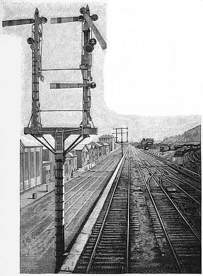
Semaphore Signal with Indicators.
(One arm governs several tracks. The number of the track
which is clear is
shown on the indicator disk.)
If it is important to have efficient means of stopping trains, it is
scarcely less important to have timely information of the need of
stopping them. To give such information is the function of signals,
which, among safety appliances, must
stand next after brakes. Signals fall naturally
into two great classes: Those
which protect points of danger and govern
the movements of engines in yards, and
those which keep an interval of space between
two trains running on one track.
For the protection of switches, crossings,
junctions, and the like, signals in immense
variety have been used, and, unfortunately,
are still used; but
in the last ten or fifteen
years the semaphore
signal has
become the general
standard in the
United States, as it
long has been in
England. This consists
of a board,
called the blade or
arm, pivoted on the
post, and back of the
pivot is a heavy casting
which carries a
colored glass lens,
either green or red.
On the post is hung
a lantern. The danger position is with the blade horizontal. In
this position the lens is in front of the lamp, and the light shows
red or green, as the case may be. The safety position is with the
blade hanging about sixty degrees from the horizontal. In this
position the light of the lantern shows white. Red is the universal
danger color, and green the color of caution. Therefore, a semaphore
signal at a point of danger shows by day a blade painted
red, with the end of the blade cut square. At night it shows a
red light. At a position some distance from the point of actual
danger, but where it is desirable to warn an engine-runner that
he is likely to find the danger signal against him, a caution signal
is placed. This is a semaphore blade painted green, with the end
notched in a V-shape, or, as it is called, a fish-tail. At night this
signal shows a green light. There is nothing very remarkable
about a piece of board arranged to wag up and down on a pin
stuck through a post, but it is wonderful how much of good brains
and good breath have been expended in getting these boards to
wag harmoniously, and in getting railroad officers to understand
that a plain board, having two possible positions, is a better signal
than any more complicated form.
Section of Saxby & Farmer Interlocking Machine.
(Showing two levers and locking mechanism.
A is normal, B is reversed.)
The arrangement of a group of signals and switches in such a
way that their movements are made
mutually dependent one upon the
other, and so that it is impossible to
make these movements in any but
prearranged sequences, is called, in
railroad vernacular, "interlocking,"
and in this sense the word will be
used here. Interlocking has become
a special art. The objects which it
is sought to accomplish by interlocking,
and the admirable way in which
those objects are attained, may best
be understood from an actual example.
For that purpose we shall take
a double-track junction completely
equipped with signals, facing-point
locks, and derailing switches (p. 205).
A general view of an interlocking
frame was given on page 171 of this
volume. Two levers from such a
frame are here shown. The normal
position of the levers is forward, as lever A. When pulled back,
as lever B, the lever is said to be reversed.
Let it be supposed that a main-line train is to be passed eastward
in the direction of the arrow B. The first movement of the
signalman in the signal-tower would naturally be to lower signals
1 and 2. He attempts to pull over lever 1, but cannot move it,
and, in spite of any effort or ingenuity on his part, that signal remains
at danger. The reason is that lever 2 when normal locks
lever 1 normal. The logic of this will be at once apparent.
Clearing signal 1 is an indication to the engineer that the way is
clear, and that he may pass the junction at speed. So long as this
signal (which, it must be remembered, is a caution signal) stands
at danger he knows that he may pass it, but must be ready to stop
before he reaches No. 2, the home-signal. Therefore No. 1 must
never be lowered till all is arranged for passing the junction at
speed. As the signalman cannot lower signal 1, he attempts to
lower signal 2. Again he finds that he cannot budge the lever.
It is locked by lever No. 3. This lever works a facing-point lock,
which must be described just at this point (p. 206).
Diagram of a Double-track Junction with Interlocked Switches and
Signals.
A is the west-bound main line track; B, the east-bound; C and D are the west-bound
and east-bound branch-tracks. Nos. 1, 10, and 12 are distant signals; Nos. 2,
9, and 11, home signals; Nos. 3, 6, and 8, facing-point locks; and Nos. 4, 5, and 7
are switches. The levers which move all of these parts are placed side by side in a frame in the signal-tower. It will
be noticed that No. 7 is a switch designed merely to derail an engine on track A. A similar switch is provided on
track C, and is worked by the same lever which works junction switch No. 5. In the sketch all levers are supposed to
stand in their "normal" position, all signals are at danger, and the switches are set for the main line. The switches
themselves are not locked in this position of the facing-point lock levers.
The front rod of the switch, that is, the rod which connects the
points of the two moving rails of the switch, is pierced with two
holes placed a distance apart just equal to the throw of the switch.
In front of these holes is a bolt which is worked by a lever in the
signal-tower. After the switch is set the lock-lever is reversed
and the bolt enters one of the holes, thus securely locking the
switch in position. There is one other interesting feature of this
facing-point lock. It has happened very often that a switch has
been thrown under a moving train, splitting the train and derailing
more or less of it. This class of accidents is especially likely to
happen when train movements are very frequent, and may be prevented
by the use of the "detector-bar." This is a bar about forty
feet long, placed alongside the rail, and carried on swinging links,
like those of a parallel ruler, in such a way that any effort to move
the bar lengthwise of the rail must raise it above the top of the
rail. This bar is moved by the same lever which moves the locking-bolt.
So long as there is a wheel on the rail above the detector-bar
it cannot be moved, therefore the locking-bolt cannot be
withdrawn, and the switch cannot be moved until the train has
passed completely off it.
Split Switches with Facing-point Locks and Detector-bars.
(The rod on the right of the track is the mechanical connection to the lever in the signal-tower by which the locks and
detector-bars are moved.)
We left the signalman trying to lower signal No. 2; vainly, because
No. 3 lever was still normal and the switch unlocked (Diagram,
p. 205). Probably he would not have begun his operations
in the bungling way that has
been supposed, but would have
first reversed lever 3. That
locks the switch by the facing-point
lock, and locks also
switch-lever 4 in the frame in
the signal-tower and releases
lever 2. Then he reverses
lever 2. That locks lever 3
and releases lever 1. Then he
reverses lever 1, which locks
lever 2. Now the way is made
for a train to pass east on the
main line, and the signals are
clear. The last signal could
not have been lowered until
the chain of operations was complete; none of the levers can now
be moved until lever 1 is again put normal and signal 1 made
to show danger. There is one point of great danger in this particular
train-movement which has not been mentioned; that is, the
crossing of main-line east-bound track B by the branch-line west-bound
track C. It will be noticed that with the levers normal, derailing
switch 5 is open, and it is impossible for a locomotive to
pass beyond it. Lever 5 is interlocked in the tower with lever 4
in such a way that, before 5 can be reversed to let a train pass
west from C, lever 4 must be reversed to trap any train on B and
turn it down the branch D. It must not be understood that the
use of "derailers" is universal. In fact, they are not recommended
by the best signal engineers, except in special conditions. In the
absence of derailer No. 5, signals 11 and 12 would be interlocked
with switch 4, so that, so long as that switch stands open for the
main line a clear signal cannot be given to a train coming west on
C. It will be noticed that signal 2 carries two semaphores on one
post. The upper one is for the main line and the lower one for
the branch. Both are operated by one lever, 2, and whether reversing
lever 2 lowers the main-line signal or the branch signal
depends on the position of the switch. The switch is made to pick
out its signal by an ingenious but very simple little arrangement,
called a selector, which is placed somewhere in the line of ground
connections.
It would be an interesting study, were there space, to follow
the possible and proper combinations of movements to pass trains
over the various tracks. It will be seen that, by concentrating the
levers which move switches and signals in one place and interlocking
them, it is made mechanically impossible for a signalman
to give a signal which would lead to a collision or a derailment
within the region under his control. The only danger at such
points is that an engineer may overrun the signals. This description
of the objects and the capacity of the system of interlocking is
no fancy sketch. The system has been in use for many years,
doing just what has been here described, and more. A recent
close estimate gave the number of interlocked levers now in use in
the United States as about eight thousand, and the number is rapidly
increasing. Recent official reports showed that in Great
Britain and Ireland there were thirty-eight thousand cases in which
a passenger line was connected with or crossed by another line,
siding, or cross-over. In eighty-nine per cent. of these cases the
levers operating the switches and protecting signals were interlocked.
The example of interlocking which has been given is one of the
simplest; the principle is capable of almost indefinite expansion,
and any one lever may be made to lock any one or more levers
among hundreds in the same frame. The greatest number of
levers assembled in any one signal-tower in this country is one
hundred and sixteen, at the Grand Central Station in New York.
In the London Bridge tower there are two hundred and eighty
levers. This is probably the greatest number in any one tower in
the world. All of these levers may be more or less interlocked.
The same principle is applied to the locking of two levers at a single
switch, and to the protection of drawbridges and highway
crossings.
The mechanism by which the interlocking is done is strong and
comparatively simple, but a detailed description of it seems out of
place here. Two levers from a Saxby & Farmer machine are
shown on page 204, with lever A normal and B reversed. The
locking mechanism is in front of the levers, and is actuated not by
the levers themselves, but by their catch-rods. It follows that it is
not the actual movement of a signal which prevents the movement
of other signals, or of switches, but it is the intention to move that
signal. This principle of "preliminary locking" is one of great
importance.
Switches and signals are often worked at such distances from
the tower that it is impossible for the operator to know whether or
not the movement contemplated has taken place. The British
Board of Trade does not permit switches to be worked more than
750 feet away. In this country there is no limit, but probably 800
feet is very rarely exceeded. Signals are worked in England up
to 3,000 or 3,500 feet very commonly, and they are even worked
a mile away, but not satisfactorily. This is with direct mechanical
connection, by rod or wire, from the levers. It is obvious that a
break in the connections between the lever and the switch or
signal might take place, and the lever be pulled over, without having
produced the corresponding movement at the far end. The
locking mechanism in the tower would not be affected by such an
accident, and consequently conflicting signals might be given.
Even this contingency is provided against with almost perfect
safety. If a signal connection breaks, the signal is counter-weighted
to go to danger. The worst that can happen is to delay
traffic. If a switch connection breaks, the locking-bolt, in the
latest form of facing-point lock, will not enter the hole in the
switch-rod, and consequently warning is given in the tower that
the switch has not moved. Electric annunciators are often placed
in the signal-tower, to show on a board before the operator
whether or not the movements of switches and signals have taken
place.
Considerable work must be done in the movement of each
lever. The ground connections must be put down with great care,
as nearly straight and level as may be, well drained, and protected
from ice and snow. All of these difficulties have been overcome
in a beautiful pneumatic interlocking apparatus which has been introduced
within the last two or three years. In this system the
motive power is compressed air. Near each switch is a small
cylinder, containing a piston which is attached directly to the
switch movement. Compressed air admitted to one side or the
other of this piston moves the switch one way or the other. But,
as it would take some time for the necessary quantity of air to flow
from the signal-tower to a distant switch, a small reservoir is
placed near the switch, and the air from this reservoir is admitted
to one end or the other of the switch cylinder according to the
position of a valve. For transmitting the motion from the tower
to the valve compressed air might be used, but, as air is elastic, a
quicker movement is got by using in the pipes some liquid which
does not readily freeze, and which, being practically non-compressible,
transmits an impulse given at one end almost instantly to
the other. The signals are worked in essentially the same manner
as the switches, except that the pneumatic valves are moved by
electricity. The tower apparatus of a pneumatic system in the
yard of the Pennsylvania Railroad at Pittsburg is shown in the
engraving opposite. In the front of the apparatus is seen a rank
of small handles, which can be turned from side to side with as
much ease as the keys of a piano can be depressed. Turning one
of these handles admits compressed air to the end of a pipe containing
liquid. Instantly the pressure is transmitted 500 or 1,000
feet to the valve at the switch to be moved. The small levers are
interlocked perfectly, and in that particular perform the duties of
the ordinary machine. A model of the tracks controlled is placed
before the operator, showing the switches and signals, and when
a movement is made on the ground it is at once repeated back by
electricity and duplicated on the model. This beautiful system is
due to the same genius that gave us the perfected air-brake and
the triple valve, and is the greatest improvement that has been
made in interlocking in the last dozen years.