By JOHN BOGART.
Development of the Rail—Problems for the Engineer—How Heights are Climbed—The
Use of Trestles—Construction on a Mountain Side—Engineering on Rope Ladders—Through
the Portals of a Cañon—Feats on the Oroya Railroad, Peru—Nochistongo
Cut—Rack Rails for Heavy Grades—Difficulties in Tunnel Construction—Bridge
Foundations—Cribs and Pneumatic Caissons—How Men work under Water—The
Construction of Stone Arches—Wood and Iron in Bridge-building—Great Suspension
Bridges—The Niagara Cantilever and the enormous Forth Bridge—Elevated
and Underground Roads—Responsibilities of the Civil Engineer.
There are one hundred and fifty
thousand miles of railway in the
United States: three hundred thousand
miles of rails—in length enough
to make twelve steel girdles for the
earth's circumference. This enormous
length of rail is wonderful—we do not
really grasp its significance. But the
rail itself, the little section of steel, is
an engineering feat. The change of its form
from the curious and clumsy iron pear-head of thirty years ago to
the present refined section of steel is a scientific development. It
is now a beam whose every dimension and curve and angle are
exactly suited to the tremendous work it has to do. The loads it
carries are enormous, the blows it receives are heavy and constant,
but it carries the loads and bears the blows and does its duty.
The locomotive and the modern passenger and freight cars are
great achievements; and so is the little rail which carries them all.
The railway to-day is one of the matter-of-fact associations of
our active life. We use it so constantly that it requires some little
effort to think of it as a wonderful thing; a creation of man's ingenuity,
which did not exist when our grandfathers were young. Its
long bridges, high viaducts, and dark tunnels may be remarked and
remembered by the traveller, but the narrow way of steel, the road
itself, seems but a simple work. And yet the problem of location,
the determination, foot by foot and mile by mile, of where the line
must go, calls in its successful solution for the highest skill of the
engineer, whose profession before the railway was created hardly
existed at all. Locomotives now climb heights which a few years
ago no vehicle on wheels could ascend. The writer, with some
engineer friends, was in the mountains of Colorado during the
summer of 1887, and saw a train of very intelligent donkeys loaded
with ore from the mines, to which no access could be had but by
those sure-footed beasts. Within a year one of that party of engineers
had located and was building a railway to those very
mines. No heights seem too great to-day, no valleys too deep, no
cañons too forbidding, no streams too wide; if commerce demands,
the engineer will respond and the railways will be built.
The location of the line of a railway through difficult country
requires the trained judgment of an engineer of special experience,
and the most difficult country is not by any means that which might
at first be supposed. A line through a narrow pass almost locates
itself. But the approach to a summit through rolling country is
often a serious problem. The rate of grade must be kept as light
as possible, and must never exceed the prescribed maximum. The
cuttings and the embankments must be as shallow as they can be
made—the quantities of material taken from the excavations should
be just about enough to make adjacent embankments. The curves
must be few and of light radius—never exceeding an arranged
limit. The line must always be kept as direct as these considerations
will allow—so that the final location will give the shortest
practicable economical distance from point to point. Many a mile
of railway over which we travel now at the highest speed has been
a weary problem to the engineer of location, and he has often accomplished
a really greater success by securing a line which seems
to closely fit the country over which it runs without marking itself
sharply upon nature's moulding, than if he had with apparent boldness
cut deep into the hills and raised embankments and viaducts
high over lowlands and valleys.
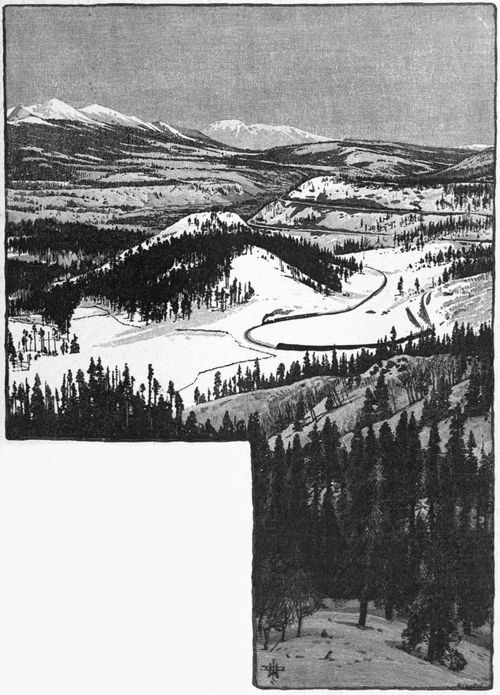
View Down the Blue from Rocky Point, Denver,
South Park and Pacific Railroad;
showing successive tiers of railway.
But roads must run through
many regions where very different
measures must be taken to
secure a location practicable for
traffic. For instance, a line at
a high elevation approaches a
wide valley which it must cross.
The rate of descent is fixed by
the established maximum grade,
and the sides of the valley are
much steeper than that rate.
Then the engineer must gain
distance—that is to say, he
must make the line long enough
to overcome the vertical height. This can often be accomplished
by carrying it up the valley on one side and down on the other.
Tributary valleys can be made use of if necessary, and the desired
crossing thus accomplished. But at times even these expedients
will not suffice. Then the line is made to bend upon itself and
wind down the hillside upon benches cut into the earth, or rock,
curving at points where nature affords any sort of opportunity, and
reaching the valley at last in long convolutions like the path of a
great serpent on the mountain side. These lines often show several
tiers of railway, one directly above the other, as may be seen
in the illustrations on pages 49 and 51.
View Down the Blue from Rocky Point, Denver, South Park
and Pacific Railroad; showing successive tiers of railway.
But roads must run through
many regions where very different
measures must be taken to
secure a location practicable for
traffic. For instance, a line at
a high elevation approaches a
wide valley which it must cross.
The rate of descent is fixed by
the established maximum grade,
and the sides of the valley are
much steeper than that rate.
Then the engineer must gain
distance—that is to say, he
must make the line long enough
to overcome the vertical height. This can often be accomplished
by carrying it up the valley on one side and down on the other.
Tributary valleys can be made use of if necessary, and the desired
crossing thus accomplished. But at times even these expedients
will not suffice. Then the line is made to bend upon itself and
wind down the hillside upon benches cut into the earth, or rock,
curving at points where nature affords any sort of opportunity, and
reaching the valley at last in long convolutions like the path of a
great serpent on the mountain side. These lines often show several
tiers of railway, one directly above the other, as may be seen
in the illustrations on pages 49 and 51.
The long trestle shown in the illustration opposite is an example
of an expedient often of the greatest service in railway construction.
These trestles are built of wood, simply but strongly framed together,
and are entirely effective for the transport of traffic for a
number of years. Then they must be renewed, or, what is better,
be replaced by embankment, which can be gradually made by
depositing the material from cars on the trestle itself. The trestle
illustrated is interesting as conforming to the curve of the line,
which in that country, the mountains of Colorado, was probably a
necessity of location.
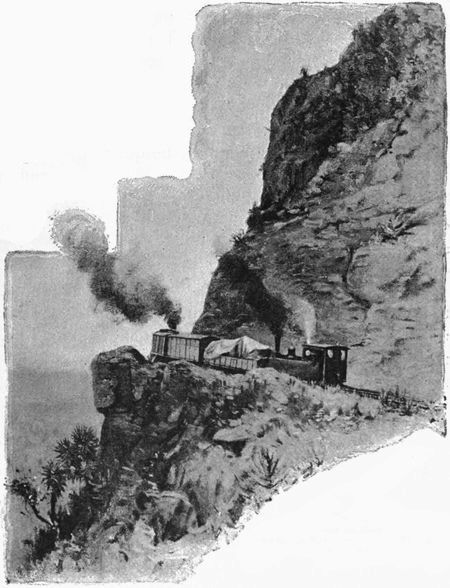
Where the direct turning of a line upon itself may not be necessary,
there may and often must be bold work done in the construction
of the road upon a mountain side. It must be supported
where necessary by walls built up from suitable foundations, often
only secured at a great depth below the grade of the road. Projecting
points of rock must be cut through, and any practicable
natural shelf or favorable formation must be made use of, as in the
picture on page 61. In some of the mountain locations, galleries
have been cut directly into the rock, the cliff overhanging the roadway,
and the line being carried in a horizontal cut or niche in the
solid wall.
Loop and Great Trestle near Hagerman's, on the Colorado Midland Railway.
The Oroya and the Chimbote railways in South America
demanded constant locations of this character. At many points
it was necessary to suspend the persons making the preliminary
measurements from the cliff above. The engineer who made these
locations told the writer that on the Oroya line the galleries were
often from 100 to 400 feet above the base of the cliff, and were generally
reached from above. Rope ladders were used to great advantage.
One 64 feet long and one 106 feet long covered the usual
practice, and were sometimes spliced together. The side ropes
were ¾ and 1¼ inches in diameter, and the rounds of wood 1¼ inches
in diameter, and 16 inches and 24 inches long. These were notched
at the ends and passed through the ropes, to which they were afterward
lashed. These ladders could be rolled up and carried about
on donkeys or mules. When swung over the side of a cliff and
secured at the top, and when practicable at the bottom, they formed
a very useful instrument in location and construction. For simple
examination of the cliff, and for rough or broken slopes not exceeding
70 to 80 degrees, an active fellow would, after some experience,
walk up and down such a slope simply grasping the rope in his
hands. If required to do any work he would secure the rope
about his body, or wind it around his arm, leaving his hands comparatively
free for light work.
The boatswain's chair—consisting of a wooden seat 6 inches
wide and two feet long, through the ends of which pass the side
ropes, looped at the top, and having their ends knotted—is a particularly
convenient seat to use where cliffs overhang to a slight
degree. The riggers were generally Portuguese sailors, who
seemed to have more agility and less fear than any other men to
be found. At Cuesta Blanca, on the Oroya, a prominent discoloration
on the cliff served as a triangulation point for locating the chief
gallery. Men were swung over the side of the cliff in a cage about
2½ feet by 6 feet, open at the top and on the side next the rock.
This was a peculiar cliff about 1,000 feet high, rising from the river
at a general slope of about 70 degrees. The grade line of the road
was 420 feet above the river. The Chileno miners climbed up a
rope ladder to a large seam near the grade, where they lived; provisions,
water, etc., being hoisted up to them. The first men sent
over the cliff to begin the preliminary work were lowered in a cage
and took their dinners with them, for fear they would not return to
the work, and that unless a genuine start was made others could
not be induced to take their places. It is safe to say that 80 per
cent. of the sixty odd tunnels on the Oroya and the seven tunnels
on the Chimbote lines were located and constructed on lines
determined by triangulation, and the results were so satisfactory
that the method may be depended upon as the best system for
determining topographical
data or
for locating and
constructing the
lines in any similar
locality.
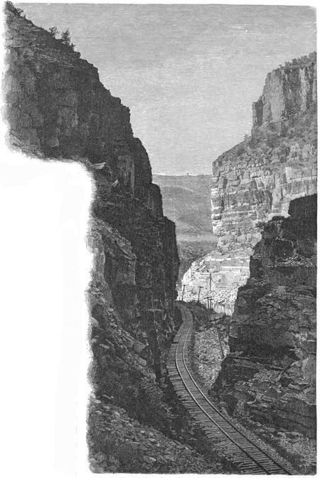
Denver and Rio Grande Railway Entering the Portals of the Grand River Cañon, Col.
Where the
rocks close in together,
as in some
of the cañons of
our Southwest,
the railway curves
about them and
finds its way often
where one would
hardly suppose a
decent wagon
road could be
built. The portals
of the Grand
River Cañon, as
here shown, present
such a line,
passing through
narrow gateways of rock rising precipitously on either side to
enormous heights.
When such a cañon or a narrow valley directly crosses the line
of the road, it must be spanned by a bridge or viaduct. The Kentucky
River Bridge, shown below, is an instance. The Verrugas
Bridge, on the Lima and Oroya Railroad in Peru, is another. This
bridge is at an elevation of 5,836 feet above sea-level. It crosses a
ravine at the bottom of which is a small stream. The bridge is
575 feet long, in four spans, and is supported by iron towers, the
central one of which is 252 feet in height. The construction was
accomplished entirely from above, the material all having been
delivered at the top of the ravine, and the erection was made by
lowering each piece to its position. This was done by the use of
two wire-rope cables, suspended across the ravine from temporary
towers at each end of the bridge.
The Kentucky River Cantilever, on the Cincinnati Southern Railway.
On the line of the same Oroya Railroad is a striking example
of the difficulties encountered in such mountain country and of the
method by which they have been overcome. A tunnel reaches a
narrow gorge, a truss is thrown across, and the tunnel continued.
Nature's wildest scenery, the deep ravine, the mountain cliffs,
and the graceful truss carrying the locomotive and train safely over
what would seem an impossible pass, here combine to give a vivid
illustration of an engineering feat.
Truss over Ravine, and Tunnel, Oroya Railroad, Peru.
The location of a part of the Mexican Central Railway through
the cut of Nochistongo is peculiarly interesting. Far underneath
the level of this line of railway there was skilfully constructed, in
1608, a tunnel which at that period was a very bold piece of engineering.
It was designed to drain the Valley of Mexico, which has
no natural outlet. This tunnel was more than six miles long and
ten feet wide. It was driven through the formation called tepetate,
a peculiar earth with strata of sand and marl. It was finished in
eleven months. At first excavated without a lining, it was afterward
faced with masonry. It was not entirely protected when a
great flood came, the dikes above gave way, and the tunnel became
obstructed. The City of Mexico was flooded, and it was decided
that, instead of repairing the tunnel an open cut should be made.
The engineer who had constructed the tunnel, Enrico Martinez,
was put in charge of this enormous undertaking, and others took
his place after his death. The cut is believed to be the largest ever
made in the world. For more than a century the work was continued.
Its greatest depth is now 200 feet. It was cut deeper, but
has partially filled with the washings from the slopes. The cost
was enormous, more than 6,000,000 dollars in silver having been
actually disbursed! Wages for workmen were then from 9 to 12
cents a day. All convicts sentenced to hard labor were put at work
in the great cut. The loss of life was very great. Writers of the
time state that more than 100,000 Indians perished while engaged
in the work.
The Nochistongo Cut, Mexican Central Railway.
The Mount Washington Rack Railroad.
When a line of railway
encountered a
grade too steep for ascent
by the traction
of the locomotive, the
earlier engineers adopted the
inclined plane. Such planes were
in use at important points during
many years. Notable instances
were those by which traffic was
carried across the Alleghany
Mountains, connecting on
each side with the Pennsylvania
railway lines. These
old planes are still visible
from the present Pennsylvania
Railroad where it
crosses the summit west of Altoona. The planes were operated
by stationary engines acting upon cables attached to the cars.
These cables passed around drums at the head of the planes, the
weight of the cars on one track partially
balancing those on the other. Similar
planes were in use also at Albany,
Schenectady, and
other places.
Trestle on Portland and Ogdensburg Railway,
Crawford Notch, White Mountains.
Another effective
expedient is the central
rack rail. No
better or more successful
example of
this method of construction
can be given
than the Mount
Washington Railway,
illustrated above.
The road was completed
in 1869. Its
length is 31/3 miles and
its total rise 3,625 feet. Its steepest grade is about 1 foot rise in
every 3 feet in length; the average grade is 1 in 4. It is built of
heavy timber, well bolted to the rock. Low places are spanned by
substantial trestle work. The gauge of the road is 4 feet 7½ inches,
and it is provided with the two ordinary rails and also the central
rack rail, which is really like an iron ladder, the sides being of
angle iron and the cross-pieces of round iron 1½ inches in diameter
and 4 inches apart. Into these plays the central cog-wheel on the
locomotive, which thus climbs this iron ladder with entire safety.
Very complete arrangements are made to control the descent of the
train in case of accident to the machinery. The locomotive is always
below the train, and pushes it up the mountain. Many thousands
of passengers have been transported every year without accident.
The rack railroad ascending the Righi, in Switzerland, was
copied after the Mount Washington
line. Some improvements in
the construction of the rack rail
and attachments have been introduced
upon mountain roads in
Germany, and this system seems
very advantageous for use in exceptionally
steep locations.
When a line of railway meets
in its course a barrier of rock, it is
often best to cut directly through.
If the grade is not too far below
the surface of the rock, the cut is
made like a great trench with the
sides as steep as the nature of
the material will allow. Very deep
cuts are, however, not desirable. The rains bring down upon
their slopes the softer material from above, and the frost detaches
pieces of rock which, falling, may result in serious accidents to
trains. Snow lodges in these deep cuts, at times entirely stopping
traffic, as in the blizzard near New York, in March, 1888.
A tunnel, therefore, while perhaps greater in first cost than a moderately
deep cut, is really often the more economical expedient.
Tunnel at the Foot of Mount St. Stephen, on the Canadian Pacific.
(The glacier 8,200 feet above the Railway.)
Peña de Mora
on the La Guayra and Carácas Railway, Venezuela.
And here is as good a place, perhaps, as any other in this
chapter, to say that true engineering is the economical adaptation
of the means and opportunities existing, to the end desired. Civil
engineering was defined, by one of the greatest of England's engineers,
as "the art of directing the great sources of power in nature
for the use and convenience of man," and that definition was
adopted as a fundamental idea in the charter of the English Institution
of Civil Engineers. But the development of engineering works
in America has been effected successfully by American engineers
only because they have appreciated another side of the
problem presented to them. A past president of the American
Society of Civil Engineers, a man of rare judgment and remarkable
executive ability, the late Ashbel Welch, said, in discussing a
great undertaking proposed by an eminent Frenchman: "That is
the best engineering, not which makes the most splendid, or even
the most perfect, work, but that which makes a work that answers
the purpose well, at the least cost." And it may be remarked, as
to the project which he was then
discussing, that after a very large
expenditure and an experience of
eight years since that discussion,
the plans of the work were modified
and the identical suggestions
made by Mr. Welch of a radical
economical change were adopted
in 1888.[8] Another eminent
American
engineer,
whose practical
experience
has
been gained
in the construction
and
engineering
supervision
of more than
five thousand
miles of railway,
said, in
his address
as President
of the American
Society
of Civil Engineers: "The high object of our profession is to consider
and determine the most economic use of time, power, and matter."
Peña de Mora
on the La Guayra and Carácas Railway, Venezuela.
And here is as good a place, perhaps, as any other in this
chapter, to say that true engineering is the economical adaptation
of the means and opportunities existing, to the end desired. Civil
engineering was defined, by one of the greatest of England's engineers,
as "the art of directing the great sources of power in nature
for the use and convenience of man," and that definition was
adopted as a fundamental idea in the charter of the English Institution
of Civil Engineers. But the development of engineering-works
in America has been effected successfully by American engineers
only because they have appreciated another side of the
problem presented to them. A past president of the American
Society of Civil Engineers, a man of rare judgment and remarkable
executive ability, the late Ashbel Welch, said, in discussing a
great undertaking proposed by an eminent Frenchman: "That is
the best engineering, not which makes the most splendid, or even
the most perfect, work, but that which makes a work that answers
the purpose well, at the least cost." And it may be remarked, as
to the project which he was then
discussing, that after a very large
expenditure and an experience of
eight years since that discussion,
the plans of the work were modified
and the identical suggestions
made by Mr. Welch of a radical
economical change were adopted
in 1888.[8] Another eminent
American
engineer,
whose practical
experience
has
been gained
in the construction
and
engineering
supervision
of more than
five thousand
miles of railway,
said, in
his address
as President
of the American
Society
of Civil Engineers: "The high object of our profession is to consider
and determine the most economic use of time, power, and matter."
Perspective View of St. Gothard Spiral Tunnels, in the Alps.
That true economy, which
finally secures in a completed
work the best results from the
investment of capital, in first
cost and continued maintenance, is an essential element in the consideration
of any really great engineering feat.
The difficulties involved in the construction of a tunnel, after
the line and dimensions have been determined, depend generally
upon the nature of the material found as the work advances. Solid
rock presents really the fewest difficulties, but it is seldom that
tunnels of considerable length occur without meeting material
which requires special provision for successful treatment. In some
cases great portions of the rock, where the roof of the tunnel is to
be, press downward with enormous weight, being detached from
the adjacent mass by the occurrence of natural seams.
Perspective View of St. Gothard Spiral Tunnels, in the
Alps.
That true economy, which
finally secures in a completed
work the best results from the
investment of capital, in first
cost and continued maintenance, is an essential element in the consideration
of any really great engineering feat.
The difficulties involved in the construction of a tunnel, after
the line and dimensions have been determined, depend generally
upon the nature of the material found as the work advances. Solid
rock presents really the fewest difficulties, but it is seldom that
tunnels of considerable length occur without meeting material
which requires special provision for successful treatment. In some
cases great portions of the rock, where the roof of the tunnel is to
be, press downward with enormous weight, being detached from
the adjacent mass by the occurrence of natural seams.
At other places soft material may be encountered, and the passage
then is attended with great difficulty. Temporary supports,
generally of timber, and of great strength, have often to be used
at every foot of progress to prevent the material from forcing its
way into the excavation already made.
In long tunnels the ventilation is a difficult problem, although
the use of compressed air drills has aided greatly in its solution.
Plan of St. Gothard Spiral Tunnels.
Among the great tunnels which have been excavated, the St.
Gothard is the most remarkable. It is 9¼ miles long, with a section
26¼ feet wide by 192/3 feet high. The work on this tunnel was
continuous, and it required 9¼
years for its completion.
The Mont Cenis tunnel, 81/3
miles in length, was completed
in 12 years.
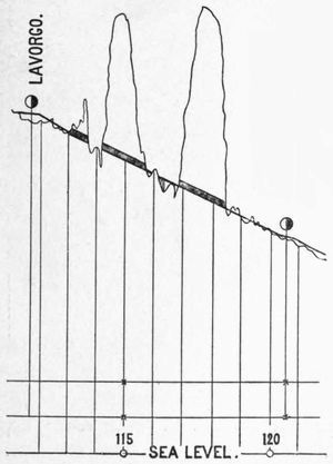
Profile of the Same.
The Hoosac Tunnel, 4¾
miles in length, 26 feet wide
and 21½ feet high, was not prosecuted
continuously; it was
completed in 1876. These tunnels are notable chiefly on account
of their great length; there are others of more moderate extent
which have peculiar features; one, illustrated on the preceding
page, is unique. This tunnel is a portion of the St. Gothard Railway,
and not very far distant from the great tunnel referred to
above. In the descent of the mountain it was absolutely necessary
to secure a longer distance than a straight
line or an ordinary curve would give; the
line was therefore doubly curved upon itself.
It enters the mountain at a high elevation,
describes a circle through the rock and,
constantly descending, reappears under itself
at the side; still descending, it enters
the mountain at another point and continues
in another circular tunnel
until it finally emerges again,
under itself, but at a comparatively
short horizontal distance
from its first entry, having gained
the required descent by a continued
grade through the tunnels.
The profile above shows the descent,
upon a greatly reduced
scale, the heavy lines marking
where the line is in the tunnel.
Portal of a Finished Tunnel; showing Cameron's Cone, Colorado.
Portal of a Tunnel in Process of Construction.
The remarkable success achieved by engineers in securing
suitable foundations at great depths is, of course, hardly known to
the thousands who constantly see the structures supported on
those foundations, but in any fair consideration of such engineering
achievements this must not be omitted. The beautiful bridge
built by Captain Eads over the Mississippi River at St. Louis,
bold in its design and excellent in its execution, is an object of admiration
to all who visit it, but the impression of its importance
would be greatly magnified if the part below the surface of the
water, which bears the massive towers, and which extends to a
depth twice as great as the height of the pier above the water,
could be visible.
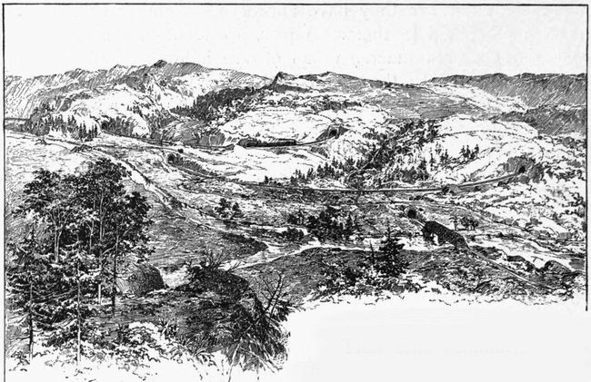
Railway Pass at Rocky Point in the Rocky Mountains.
The simplest and most effective foundation is, of course, on
solid rock. In many localities reliable foundations are built upon
earth, when it exists at a suitable depth and of such a character as
properly to sustain the weight. Foundations under water, when
rock or good material occurs at moderate depth, are constructed
frequently by means of the coffer-dam, which is simply an enclosure
made water-tight and properly connected with the bottom of
the stream. The water is then pumped out and the foundation
and masonry built within this temporary dam. When the material
is not of a character to sustain the weight, the next expedient
is the use of piles, which are driven into the ground, often to a
very considerable depth, and sustain the load placed upon them by
the friction upon the sides of the piles of the material in which they
are driven. It is seldom that dependence is placed upon the load
being transferred from the top to the point of the pile, even though
the point may have penetrated to a comparatively solid material.
Wood is generally used for piles, and where the ground is permanently
saturated there seems to be hardly any known limit to
its durability. The substructure of foundations, where it is certain
that they will always be in contact with water, can be, and
generally is, of wood, and the permanency of such foundations
is well established. An exception to this, however, occurs in
salt-water, particularly in warmer countries, where the ravages of
the minute Teredo Navalis, and of the still more minute Limnoria
Terebrans, destroy the wood in a very short period of time.
These insects, however, do not work below the ground-line or bed
of the water. In many special cases hollow
iron piles are used successfully.
Bridge Pier Founded on Piles.
The ordinary method of forcing a pile into
the ground is by repeated blows of a hammer
of moderate weight; better success being obtained
by frequent blows of the hammer, lifted
to a slight elevation, than results from a greater
fall, there being danger also in the latter case
of injuring the material of the pile. The use
of the water-jet for sinking piles, particularly in
sand, is interesting. A tube, generally
of ordinary gas-pipe, open at the lower
end, is fastened to the pile; the upper
end is connected by a hose to a powerful
pump and, the pile being placed in
position on the surface of the sand,
water is forced through the tube and
excavates a passage for the pile, which,
by the application of very light pressure,
descends rapidly to the desired depth.
The stream of water must be continuous,
as it rises along the side of the pile
and keeps the sand in a mobile state.
Immediately upon the cessation of pumping,
the sand settles about the pile, and
it is sometimes quite impossible to afterward
move it. The water-jet is used in
sinking iron piles by conducting the
water through the interior of the hollow pile and out of a hole at
its point. The piles of the great iron pier at Coney Island were
sunk with great celerity in this way. The illustration opposite
shows one of the piers of a bridge founded upon wooden piling.
In many cases it would be impossible to drive piling in such a
way as to insure the durability of the structure above it. This is
particularly true of the foundations of structures crossing many of
our rivers, where the bottom is of material which, in time of flood,
sometimes scours to very remarkable depths; the material often
being replaced when the flood has subsided. The expedient
adopted is the pneumatic tube, or the caisson. Both are merely
applications of the well-known principle of the diving-bell. In the
former case hollow iron tubes, open at the bottom, are sunk to
considerable depths, the water being expelled by air pumped into
the tubes at a pressure sufficient to resist the weight of the water.
Entrance to the tubes is obtained by an air-lock at the top, the
material is excavated from the inside, and sufficient weight placed
upon the tube to force it gradually to the desired depth. When
that depth is attained, the tubes are filled with concrete, and thus
solid pillars of hydraulic concrete, surrounded by cast-iron tubing,
are obtained.
The pneumatic caisson is an enlargement of this idea of the diving-bell.
The caisson is simply a great chamber or box, open at
the bottom; the outside bottom edges are shod and cased with
iron so as to give a cutting surface; the roof and sides are made
of timber, thoroughly bolted together, and of such strength as to
resist the pressure of the structure to be finally founded upon it.
The chamber in the open bottom is of sufficient height to enable
the laborers to work comfortably in it. This caisson is generally
constructed upon the shore in the vicinity of the structure and
towed to the point where the foundation is to be sunk. Air is supplied
by powerful pumps and is forced into the working chamber.
The pressure of the air of course increases constantly as
the caisson descends; it must always be sufficient to overbalance
the weight of the water and thus prevent the water from entering
the chamber.
Descent to the caisson is made through a tube, generally of
wrought iron, and having, at a suitable point, an air-lock, which is
substantially an enlargement of the tube, forming a chamber, and
of sufficient size to accommodate a number of men. This air-lock
is provided with doors or valves at the top and at the bottom, both
opening downward, and also with small tubes connecting the air-lock
with the chamber below and with the external air above.
Entrance to the caisson is effected through this air-lock. The
lower door, or valve, being at the bottom, closes and is kept closed
by the pressure of the air in the caisson below. After the air-lock
is entered the upper door or valve is shut, and held shut a few
moments, and the tube connecting with the outer air is closed; a
small valve in the tube connecting with the caisson is then opened
gradually and the pressure in the air-lock becomes the same as
that in the chamber below; as soon as this is effected the valve,
or door, at the bottom of the air-lock falls open and the air-lock
becomes really a part of the caisson.
A sufficient force of men is employed in the chamber to gradually
excavate the material from its whole surface and from under
the cutting edge, and the masonry structure is founded upon the
top of the caisson and built gradually, so as to give constantly a
sufficient weight to carry the whole construction down to its final
location upon the stable foundation, which may be the bed-rock or
may be some strata of permanent character.
The problem of lighting the chamber was until recently of considerable
difficulty. The rapid combustion under great pressure
made the use of lamps and candles very troublesome, particularly
on account of the dense smoke and large production of lampblack.
The introduction of the electric light has greatly aided in the
more comfortable prosecution of pneumatic foundation work.
Transverse Section of Pneumatic Caisson.
The removal of rock, or any large mass, from the caisson is effected
through the air-chamber; but the removal of finer material,
as sand or earth, is accomplished by the sand pump or by the
pressure of the air. A tube, extending from the top of the masonry
and kept above the surface by additions, as may be required,
enters the working chamber and is controlled by proper valves.
Lines of tubing and hose extend to all portions of the chamber.
A slight excavation is made and kept filled with water. The bottom
of the tube, or the hose connected with it, is placed in this
excavation, and, the material being agitated so as to be in suspension
in the water, the valve is opened, and the pressure of the air
throws the water and the material held in suspension to the surface,
through the tube, from the end of which it is projected with
great velocity and may be deposited at any desired adjacent point.
This method, however, exhausts the air from the caisson too rapidly
for continuous service. The Eads sand-pump is therefore
generally used. This is an ingenious apparatus, somewhat the
same in principle as the injector which forces water into steam-boilers.
A stream of water is thrown by a powerful pump through
a tube which, at a point near the inlet for the excavated material,
is enlarged so as to surround another tube. The water is forced
upward with great velocity into the second tube, through a conical
annular opening, and, expelling the atmosphere, carries with it to
the surface a continuous stream of sand and water from the bottom
of the excavation.
This system has been used successfully in the foundations of
piers and abutments of bridges in all parts of the world. The
rapidity of the descent of the caisson varies with the material
through which it has to pass. The speed with which such foundations
are executed is remarkable, when one remembers with what
delicacy and intelligent supervision they have to be balanced and
controlled. In some instances it has been necessary to carry them
to great depths, one at St. Louis being 107 feet below ordinary
water level in the river.
The pressure of air in caissons at these depths is very great;
at 110 feet below the surface of the water it would be 50 pounds
to the square inch. Its effect upon the men entering and working
in the caisson has been carefully noted in various works, and these
effects are sometimes very serious; the frequency of respiration is
increased, the action of the heart becomes excited, and many persons
become affected by what is known as the "caisson disease,"
which is accompanied by extreme pain and in some cases results
in more or less complete paralysis. The careful observations of
eminent physicians who have given this disease special attention
have resulted in the formulation of rules which have reduced the
danger to a minimum.
At Work in a Pneumatic Caisson—fifty feet below the surface of the water.
The execution of work within a deep pneumatic caisson is worth
a moment's consideration. Just above the surface of the water
is a busy force engaged in laying the solid blocks of masonry
which are to support the structure. Great derricks lift the stones
and lay them in their proper position. Powerful pumps are forcing
air, regularly and at uniform pressure, through tubes to the chamber
below. Occasionally a stream of sand and water issues with
such velocity from the discharge pipe that, in the night, the friction
of the particles causes it to look like a stream of living fire. Far
below is another busy force. Under the great pressure and abnormal
supply of oxygen they work with an energy which makes
it impossible to remain there more than a few hours. The water
from without is only kept from entering by the steady action of the
pumps far above and beyond their control. An irregular settlement
might overturn the structure. Should the descent of the
caisson be arrested by any solid under
its edge, immediate and judicious action
must be taken. If the obstruction be a
log, it must be cut off outside the edge
and pulled into the chamber. Boulders
must be undermined and often must be
broken up by blasting. The excavation
must be systematic and regular. A constant
danger menaces the lives of these
workers, and the wonderful success with
which they have accomplished what they
have undertaken is entitled to notice and
admiration.
Pier of Hawkesbury Bridge, Australia.
Another process, which has succeeded
in carrying a foundation to greater depths
than is possible with compressed air, is
by building a crib or caisson, with chambers
entirely open at the top, but having
the alternate ones closed at the bottom
and furnished with cutting edges. These
closed chambers are weighted with stone
or gravel until the structure rests upon
the bottom of the river; the material is
then excavated from the bottom through
the open chambers, by means of dredges,
thus permitting the structure to sink by
its weight to the desired depth. When that depth is reached, the
chambers which have been used for dredging are filled with concrete,
and the masonry is constructed upon the top of this structure.
The use of this system has enabled the engineer to place
foundations deeper than has been accomplished by any other device,
one recently built in Australia being 175 feet below the surface
of the water. The illustrations above and on page 76 show
this method of construction.