Foundation Crib of the Poughkeepsie Bridge.
Even more remarkable than the pneumatic caisson is this
method of sinking these great foundations. The removal of material
must be made with such systematic regularity that the structure
shall descend evenly
and always maintain
its upright position.
The dredge is handled
and operated entirely
from the surface. The
very idea is startling,
of managing an excavation
more than a
hundred feet below the
operator, entirely by
means of the ropes
which connect with the dredge, and doing it with such delicacy
that the movement of an enormous structure, weighing many tons,
is absolutely controlled. This is one of the latest and most interesting
advances of engineering skill.
Transverse Section of the same.
While it is true that the avoidance of large expenditure, when
possible, is a mark of the best engineering, yet great structures
often become absolutely necessary in the development of railway
communication. Wide rivers must be crossed, deep valleys must
be spanned, and much study has been given to the best methods
of accomplishing these
results. In the early
history of railways in
Europe substantial
viaducts of brick and
stone masonry were
generally built; and in
this country there are
notable instances of
such constructions.
The approach to the
depot of the Pennsylvania
Railroad, in the city of Philadelphia, is an excellent example.
Each street crossed by the viaduct is spanned by a bold arch of
brick. Upon a
number of our railways there
are heavy masonry arches and culverts,
and at some places these are of a very
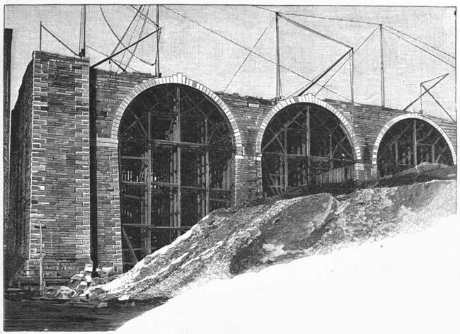
interesting character. The arches in
the approach to the bridge over the
Harlem Valley (recently completed) are shown above. They
are of granite, having a span of 60 feet. The illustration shows
also the method of supporting the stone work of such arches during
construction. Braced timbers form what is called the centre,
and support the curved frame of plank upon which the masonry
is built, which, of course, cannot be self-supporting until the keystone
is in place; then the centre is lowered by a loosening of the
wedges which support it, and the stone work of the arch is permitted
to assume its final bearing. It is generally considered that
where it is practicable to construct masonry arches under railways
there is a fair assurance of their permanency, but some engineers
of great experience in railway construction advance the theory that
the constant jar and tremor produced by passing railway trains is
really more destructive to masonry work than has been supposed,
and that it may be true that the elements of the best economy will
be found in metal structures rather than in masonry. It is a fact
that repairs and renewals of metal bridges are much more easily
accomplished than of masonry constructions.
Granite Arched Approach to
Harlem River
Bridge in
Process of Construction.
In this country
the wooden bridge
has been an important,
in fact an essential element
in the successful building
of our railways.
Timber is also used extensively
in railroad construction
in the form of trestles; one
example of which has been
alluded to on page 50. There were also constructed, years ago,
some very bold viaducts in wood. One of the most interesting is
shown above, being the viaduct at Portage, N. Y. This construction
was over 800 feet long, and 234 feet high from the bed of
the river to the rail. The masonry foundations were 30 feet high,
the trestles 190 feet, and the truss 14 feet; it contained more than a
million and a half feet, board measure, of timber. The timber piers,
which were 50 feet apart, are formed by three trestles, grouped together.
It was framed so that defective pieces could be taken out
and replaced at any time. This bridge was finished in 1852 and
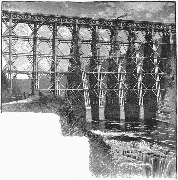
was completely destroyed by fire in 1875. The new metal structure
which took its place is shown on the opposite page, and is an
interesting example of the American method of metal viaduct construction,
an essential feature of that construction being the concentration
of the material into the least possible number of parts. This
bridge has ten spans of 50 feet, two of 100 feet, and one of 118 feet.
The trusses are of what is called the Pratt pattern, and are supported
by wrought-iron columns, two pairs of columns forming a skeleton
tower 20 feet wide and 50 feet long on the top. There are six of
these towers, one of which has a total height from the masonry to
the rail of 203 feet 8 inches. There are over 1,300,000 pounds of
iron in this structure.
Granite Arched Approach to Harlem River
Bridge in Process of Construction.
In this country
the wooden bridge
has been an important,
in fact an essential element
in the successful building
of our railways.
Timber is also used extensively
in railroad construction
in the form of trestles; one
example of which has been
alluded to on page 50. There were also constructed, years ago,
some very bold viaducts in wood. One of the most interesting is
shown above, being the viaduct at Portage, N. Y. This construction
was over 800 feet long, and 234 feet high from the bed of
the river to the rail. The masonry foundations were 30 feet high,
the trestles 190 feet, and the truss 14 feet; it contained more than a
million and a half feet, board measure, of timber. The timber piers,
which were 50 feet apart, are formed by three trestles, grouped together.
It was framed so that defective pieces could be taken out
and replaced at any time. This bridge was finished in 1852 and
was completely destroyed by fire in 1875. The new metal structure
which took its place is shown on the opposite page, and is an
interesting example of the American method of metal viaduct construction,
an essential feature of that construction being the concentration
of the material into the least possible number of parts. This
bridge has ten spans of 50 feet, two of 100 feet, and one of 118 feet.
The trusses are of what is called the Pratt pattern, and are supported
by wrought-iron columns, two pairs of columns forming a skeleton
tower 20 feet wide and 50 feet long on the top. There are six of
these towers, one of which has a total height from the masonry to
the rail of 203 feet 8 inches. There are over 1,300,000 pounds of
iron in this structure.
The Old Portage Viaduct,
Erie Railway, N. Y.
The fundamental idea of a bridge is a simple beam of wood.
If metal is substituted it is still a beam with all superfluous parts
cut away. This results in what is called an I beam. When
greater loads have to be carried, the I beam is enlarged and
built up of metal plates riveted together and thus becomes a plate
girder. These are used for all short railway spans. For greater
spans the truss must be employed.
The Old Portage Viaduct, Erie Railway, N. Y.
The fundamental idea of a bridge is a simple beam of wood.
If metal is substituted it is still a beam with all superfluous parts
cut away. This results in what is called an I beam. When
greater loads have to be carried, the I beam is enlarged and
built up of metal plates riveted together and thus becomes a plate
girder. These are used for all short railway spans. For greater
spans the truss must be employed.
Before referring, however, to examples of truss bridges, a description
should be given of the Britannia Bridge, built by Robert
Stephenson in 1850, over the Menai Straits. This great construction
carries two lines of rails and is built of two square tubes,
side by side, each being continuous, 1,511 feet long, supported at
each extremity and at three intermediate points, and having two
spans of 460 feet each and two spans of 230 feet each. The towers
which support this structure are of very massive masonry, and
rise considerably above the top of the tubes. These tubes are
each 27 feet high and 14 feet 8 inches wide; they are built up of
plate iron, the top and bottom being cellular in construction, and
the sides of a single thickness of iron. The tubes for the long
spans were built on shore and floated to the side of the bridge and
then lifted by hydraulic presses to their final position. The rapid
current, and other considerations, made the erection of false works
for these spans impracticable. The beautiful suspension bridge,
built by Telford in 1820, over the Menai Straits, is only a mile
away from this Britannia Bridge, but, at the time of the construction
of the latter, it was not deemed possible by English engineers
to erect a suspension bridge of sufficient strength and stability to
accommodate railway traffic.
The Britannia Tubular Bridge over the Menai Straits, North Wales.
The Victoria Bridge at Montreal is of the same general character
of construction as the Britannia Bridge, but is built only for
a single line of rails; this bridge also was built by Mr. Stephenson,
in 1859. These two structures were enormous works; their
strength is undoubted, but they lack that element of permanent
economy which has been spoken of in this article; their cost was
very great, and the expense of maintenance is also very great. A
very large amount of rust is taken from these tubes every year;
they require very frequent painting, and there are on the Victoria
Bridge 30 acres of iron surface to be thus painted.
Old Stone Towers of the Niagara Suspension Bridge.
A remarkable and interesting contrast to these heavy tubes of
iron is the Niagara Falls railway suspension bridge, completed in
March, 1855. The span of this bridge is 821 feet, and the track
is 245 feet above the water surface. It is supported by 4 cables
which rested on the tops of two masonry towers at each end of the
central span, the ends of the cables being carried to and anchored
in the solid rock. The suspended superstructure has two floors,
one above the other, connected together at each side by posts and
truss rods, inclined in such a manner as to form an open trussed
tube, not intended to support the load, but to prevent excessive
undulations. The floors are suspended from the cables by wire
ropes, the upper floor carrying the railroad track, and the lower
forming a foot and carriage way. Each cable has 3,640 iron wires.
This bridge carried successfully a heavy traffic for 26 years; it was
then found that some repairs to the cable were required at the anchorage,
the portions of the cables exposed to the air being in excellent
condition. These repairs were made, and the anchorage
was substantially reinforced. At the same time it was found that
the wooden suspended superstructure was in bad condition, and
this was entirely removed and replaced by a structure of iron, built
and adjusted in such a manner as to secure the best possible results.
For some time it had been noticed that the stone towers
which supported the great cables of the bridge showed evidences
of disintegration at the surface, and a careful engineering examination
in 1885 showed that these towers were in a really dangerous
condition. The reason for this was that the saddles over which
the cables pass on the top of the towers had not the freedom of
motion which was required for the action of the cables, caused by
differences of temperature and by passing loads. These saddles
had been placed upon rollers but, at some period, cement had been
allowed to be put between these rollers, thus preventing their free
motion. The result was a bending
strain upon the towers which
was too great for the strength
and cohesion of the stone.
A most interesting and successful
feat was accomplished
in the substitution of iron
towers for these stone towers,
without interrupting
the traffic across the bridge.
This was accomplished within
a year or two by building
a skeleton iron tower outside
of the stone tower, and
transferring the cables from the stone to the iron tower by a most
ingenious arrangement of hydraulic jacks. The stone towers were
then removed. Thus, by the renewal of its suspended structure
and the replacing of its towers, the bridge has been given a new
lease of life and is in excellent condition to-day.
The New Iron Towers of the Same.
This Niagara railway
suspension bridge has
been so long in successful
operation that it is difficult
now to appreciate the general
disbelief in the possibility
of its success as a
railway bridge, when it
was undertaken. It was
projected and executed by
the late John A. Roebling.
Before it was finished, Robert
Stephenson said to him,
"If your bridge succeeds,
mine is a magnificent blunder." The Niagara bridge did succeed.
Below the Brooklyn Bridge.
From a painting by J. H. Twachtman.
We are so familiar with the great suspension bridge between
New York and Brooklyn, that only a simple statement of some of
its characteristic features will be given. Its clear span is 1,595½
feet. With its approaches its length is 3,455 feet. The clear
waterway is 135 feet high. The towers rise 272 feet above high
water and extend on the New York side down to rock 78 feet below.
The four suspension cables are of steel wire and support six
parallel steel trusses, thus providing two carriage ways, two lines
of railway, and one elevated footway. The cables are carried to
bearing anchorages in New York and in Brooklyn. The cars on
the bridge are propelled by cables, and the amount of travel is
now so great as to demand some radical changes in the methods
for its accommodation, which a few years ago were supposed to
be ample.
Except under special circumstances of location or length of
span, the truss bridge is a more economical and suitable structure
for railway traffic than a suspension bridge.
The advance from the wood truss to the modern steel structure
has been through a number of stages. Excellent bridges were
built in combinations of wood and iron, and are still advocated
where wood is inexpensive. Then came the use of cast iron for
those portions of the truss subject only to compressive strains,
wrought iron being used for all members liable to tension. Many
bridges of notable spans were built in this way and are still in use.
The form of this combination truss varied with the designs of different
engineers, and the spans extended to over three hundred
feet. The forms bore the names of the designers, and the Fink,
the Bollman, the Pratt, the Whipple, the Post, the Warren, and
others had each their advocates. The substitution of wrought for
cast iron followed, and until quite recently trusses built entirely of
wrought iron have been used for all structures of great span. The
latest step has been made in the use of steel, at first for special
members of a truss and latterly for the whole structure. The art
of railway bridge building has thus, in a comparatively few years,
passed through its age of wood, and then of iron, and now rests in
the application of steel in all its parts.
Two distinct ways of connecting the different parts of a structure
are in common use, riveting and pin connections.
In riveted connections the various parts of the bridge are fastened
at all junctions by overlapping the plates of iron or steel and
inserting rivets into holes punched through all the plates to be
connected. The rivets are so spaced as to insure the best result
as to strength. The pieces of metal are brought together, either
in the shop or at the structure during erection, and the rivets,
which are round pieces of metal with a head formed on one end,
are heated and inserted from one side, being made long enough to
project sufficiently to give the proper amount of metal for forming
the other head. This is done while the rivet is still hot, either by
hammering or by the application of a riveting machine, operated
by steam or hydraulic pressure. Ingenious portable machines are
now manufactured which are hung from the structure during erection
and connected by flexible hose with the steam power, by the
use of which the rivet heads can be formed in place with great
celerity. The connections of plates by rivets of proper dimensions
and properly spaced give great strength and stiffness to such
joints.
In pin connections the members of a structure are assembled
at points of junction and a large iron or steel pin inserted in a pin-hole
running through all the members. This pin is made of such
diameter as to withstand and properly transmit all the strains
brought upon it. Joints made with such pin connections have flexibility,
and the strains and stresses can be calculated with great
precision. Eye-bars are forged pieces of iron or steel, generally
flat, and enlarged at the ends so as to give a proper amount of
metal around the pin-hole or eye, formed in those ends.
Structures connected by pins at their principal junctions have,
of course, many parts in which riveting must be used.
The elements which are distinctively American in our railway
bridges are the concentration of material in few members and the
use of eye-bars and pin connections in place of riveted connections.
The riveted methods are, however, largely used in connection
with the American forms of truss construction.
Truss Bridge of the Northern Pacific Railway over the Missouri River at Bismarck, Dak.—Testing the central span.
An excellent example of an American railway truss bridge is
shown on the opposite page. This structure spans the Missouri
River at its crossing by the Northern Pacific Railroad. It has three
through spans of 400 feet each and two deck spans of 113 feet each.
The bottom chords of the long spans are 50 feet above high water,
which at this place is 1,636 feet above the level of the sea. The
foundations of the masonry
piers were pneumatic
caissons. The trusses of
the through spans, 400
feet long, are 50 feet deep
and 22 feet between centres.
They are divided
into 16 panels of 25 feet
each. The truss is of the
double system Whipple
type, with inclined end
posts. The bridge is proportioned
to carry a train
weighing 2,000 pounds
per lineal foot, preceded
by two locomotives weighing
150,000 pounds in a
length of 50 feet. The
pins connecting the members
of the main truss are
5 inches in diameter.
This bridge is a characteristic
illustration of the
latest type of American
methods. The extreme
simplicity of its lines of
construction, the direct
transfer of the strains arising
from loads, through
the members, to and from
the points where those
strains are concentrated in
the pin connections at the
ends of each member, are
apparent even to the untechnical
eye. The apparent
lightness of construction
arising from the
concentration of the material in so small a number of members,
and the necessarily great height of the truss, give a grace and
elegance to the structure, and suggest bold and fine development
of the theories of mechanics.
Curved Viaduct, Georgetown, Col.; the Union Pacific crossing its own Line.
An interesting viaduct is shown in the above illustration, where
the railway crosses its own line on a curved truss.
The truss bridges which have been mentioned as types of the
modern railway bridge are erected by the use of false works of
timber, placed generally upon piling or other suitable foundation,
between the piers or abutments, and made of sufficient strength to
carry each span of the permanent structure until it is completed
and all its parts connected, or, as is technically said, until the span
is swung. Then the false works are removed and the span is left
without intermediate support. But there are places where it
would be impossible or exceedingly expensive to erect any false
works. A structure over a valley of great depth, or over a river
with very rapid current, are instances of such a situation.
A suspension bridge would solve the problem, but in many
cases not satisfactorily. The method adopted by Colonel C. Shaler
Smith at the Kentucky River Bridge [p. 55] shows ingenuity
and boldness worthy of special remark. The Cincinnati Southern
Railroad had here to cross a cañon 1,200 feet wide and 275 feet
deep. The river is subject to freshets every two months, with a
range of 55 feet and a known rise of 40 feet in a single night.
Twenty years before, the towers for a suspension bridge had been
erected at this point. The design adopted for the railroad bridge
was based upon the cantilever principle. The structure has three
spans of 375 feet each, carrying a railway track at a height of 276
feet above the bed of the river. At the time of its construction
this was the highest railway bridge in the world, and it is still the
highest structure of the kind with spans of over 60 feet in length.
The bridge is supported by the bluffs at its ends and by two intermediate
iron piers resting upon bases of stone masonry. Each
iron pier is 177 feet high, and consists of four legs, having a base
of 71½ × 28 feet, and terminating at its top in a turned pin 12
inches in diameter under each of the two trusses. Each iron pier
is a structure complete in itself, with provision for expansion and
contraction in each direction through double roller beds interposed
between it and the masonry, and is braced to withstand a gale of
wind that would blow a loaded freight-train bodily from the bridge.
The trusses were commenced by anchoring them back to the
old towers, and were then built out as cantilevers from each bluff
to a distance of one-half the length of the side spans, and at this
point rested upon temporary wooden supports. Thence they were
again extended as cantilevers until the side spans were completed
and rested upon the iron piers. This cantilever principle is
simply the balancing of a portion of the structure on one side of a
support by the portion on the opposite side of the same support.
Similarly the halves of the middle span were built out from the
piers, meeting with exactness in mid-air. The temporary support
used first at the centre of one side span and then at the other, was
the only scaffolding used in erecting the structure, none whatever
being used for the middle span.
When the junction was made at the centre of the middle span,
the trusses were continuous from bluff to bluff, and, had they been
left in this condition, would have been subjected to constantly
varying strains resulting from the rise and fall of the iron piers
due to thermal
changes. This
liability was obviated
by cutting
the bottom chords
of the side spans and
converting them into sliding joints
at points 75 feet distant from the
iron piers. This done, the bridge
consists of a continuous girder 525 feet long, covering the middle
span of 375 feet, and projecting as cantilevers for 75 feet beyond
each pier, each cantilever supporting one end of a 300-foot span,
which completes the distance to the bluff on each side.
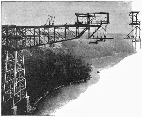
The Niagara Cantilever
Bridge in Progress.
A most interesting example of cantilever construction is the railway
bridge built several years ago at Niagara, only a few rods from
the suspension bridge and a short distance below the great falls. It
is shown in the illustrations above and on page 91. The floor of
the bridge is 239 feet above the surface of the water, which at that
point has a velocity in the centre of 16½ miles per hour and forms
constant whirlpools and eddies near the shores. The total length
of the structure is 910 feet, and the clear span over the river between
the towers is 470 feet. The shore arms of the cantilever,
that is to say, those portions of the structure which extend from
the top of the bank to the top of the tower built from the foot of
the bank, are firmly anchored at their shore ends to a pier built
upon the solid rock. These shore-arms were constructed on
wooden false works, and serve as balancing weights to the other
or river arms of the lever, which project out over the stream.
These river-arms were built by the addition of metal, piece by
piece, the weight being always more than balanced by the shore-arms.
The separate members of the river-arms were run out on
the top of the completed part and then lowered from the end by
an overhanging travelling derrick, and fastened in place by men
working upon a platform suspended below. This work was continued,
piece by piece, until the river-arm of each cantilever was
complete, and the structure was then finished by connecting these
river-arms by a short truss suspended from them directly over the
centre of the stream. This whole structure was built in eight
months, and is an example both of a bold engineering work and of
the facility with which a pin-connected structure can be erected.
The materials are steel and iron. The prosecution of this work
by men suspended on a platform, hung by ropes from a skeleton
structure projecting, without apparent support, over the rushing
Niagara torrent, was always an interesting and really thrilling
spectacle.
The Niagara Cantilever Bridge in Progress.
A most interesting example of cantilever construction is the railway
bridge built several years ago at Niagara, only a few rods from
the suspension bridge and a short distance below the great falls. It
is shown in the illustrations above and on page 91. The floor of
the bridge is 239 feet above the surface of the water, which at that
point has a velocity in the centre of 16½ miles per hour and forms
constant whirlpools and eddies near the shores. The total length
of the structure is 910 feet, and the clear span over the river between
the towers is 470 feet. The shore arms of the cantilever,
that is to say, those portions of the structure which extend from
the top of the bank to the top of the tower built from the foot of
the bank, are firmly anchored at their shore ends to a pier built
upon the solid rock. These shore-arms were constructed on
wooden false works, and serve as balancing weights to the other
or river arms of the lever, which project out over the stream.
These river-arms were built by the addition of metal, piece by
piece, the weight being always more than balanced by the shore-arms.
The separate members of the river-arms were run out on
the top of the completed part and then lowered from the end by
an overhanging travelling derrick, and fastened in place by men
working upon a platform suspended below. This work was continued,
piece by piece, until the river-arm of each cantilever was
complete, and the structure was then finished by connecting these
river-arms by a short truss suspended from them directly over the
centre of the stream. This whole structure was built in eight
months, and is an example both of a bold engineering work and of
the facility with which a pin-connected structure can be erected.
The materials are steel and iron. The prosecution of this work
by men suspended on a platform, hung by ropes from a skeleton
structure projecting, without apparent support, over the rushing
Niagara torrent, was always an interesting and really thrilling
spectacle.
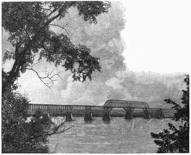
The Niagara Cantilever Bridge Completed.
The Lachine Bridge recently built over the St. Lawrence near
Montreal, illustrated below, has certain peculiar features. It has a
total length of 3,514 feet. The two channel spans are each 408 feet
in length and are through spans. The others are deck spans.
Through spans are
those where the train
passes between the
side trusses. Deck
spans are those
where the train
passes over the top
of the structure.
These two channel
spans and the two spans next them form cantilevers, and the channel
spans were built out from the central pier and from the adjacent
flanking spans without the use of false works in either channel.
A novel method of passing from the deck to the through spans has
been used, by curving the top and bottom chords of the channel
spans to connect with the chords of the flanking spans. The material
is steel.
The Lachine Bridge, on the
Canadian Pacific Railway,
near Montreal, Canada.
This structure, light, airy, and graceful, forms a strong contrast
to the dark, heavy tube of the Victoria Bridge just below.
The enormous cantilever Forth Bridge, with its two spans of
1,710 feet each, is in steady progress of construction and will when
completed mark a long step in advance in the science of bridge
construction.
The Lachine Bridge, on the Canadian Pacific Railway, near Montreal, Canada.
This structure, light, airy, and graceful, forms a strong contrast
to the dark, heavy tube of the Victoria Bridge just below.
The enormous cantilever Forth Bridge, with its two spans of
1,710 feet each, is in steady progress of construction and will when
completed mark a long step in advance in the science of bridge
construction.
Of entirely different design and principle from all these trusses
are the beautiful steel arches of the St. Louis Bridge [p. 95], the
great work of that remarkable genius, James B. Eads. This
structure spans the Mississippi at St. Louis. Difficult problems
were presented in the study of the design for a permanent bridge
at that point. The river is subject to great changes. The variation
between extreme low and high water has been over 41 feet.
The current runs from 2¾ to 8½ miles per hour. It holds always
much matter in suspension, but the amount so held varies greatly
with the velocity. The very bed of the river is really in constant
motion. Examination by Captain Eads in a diving-bell showed
that there was a moving current of sand at the bottom, of at least
three feet in depth. At low water, the velocity of the stream is
small and the bottom rises. When the velocity increases, a
"scour" results and the river-bed is deepened, sometimes with
amazing rapidity. In winter the river is closed by huge cakes of
ice from the north, which freeze together and form great fields of
ice.
It was decided to be necessary that the foundations should go
to rock, and they were so built. The general plan of the superstructure,
with all its details, was elaborated gradually and carefully,
and the result is a real feat of engineering. There are three
steel arches, the centre one having a span of 520 feet and each
side arch a span of 502 feet. Each span has four parallel arches
or ribs, and each arch is composed of two cylindrical steel tubes,
18 inches in exterior diameter, one acting as the upper and the
other as the lower chord of the arch. The tubes are in sections,
each about twelve feet long, and connected by screw joints. The
thickness of the steel forming the tubes runs from 13/16 to 21/8 inches.
These upper and lower tubes are parallel and are 12 feet apart,
connected by a single system of diagonal bracing. The double
tracks of the railroad run through the bridge adjacent to the side
arches at the elevation of the highest point of the lower tube. The
carriage road and footpaths extend the full width of the bridge and
are carried, by braced vertical posts, at an elevation of twenty-three
feet above the railroad. The clear headway is 55 feet above
ordinary high water. The approaches on each side are masonry
viaducts, and the railway connects with the City Station by a tunnel
nearly a mile in length. The illustration shows vividly the
method of erection of these great tubular ribs. They were built
out from each side of a pier, the weight on one side acting as a
counterpoise for the construction on the other side of the pier.
They were thus gradually and systematically projected over the
river, without support from below, till they met at the middle of
the span, when the last central connecting tube was put in place
by an ingenious mechanical arrangement, and the arch became
self-supporting.
The double arch steel viaduct recently built over the Harlem
Valley in the city of New York [p. 97] has a marked difference
from the St. Louis arches in the method of construction of the
ribs. These are made up of immense voussoirs of plate steel,
forming sections somewhat analogous to the ring stones of a masonry
arch. These sections are built up in the form of great I
beams, the top and bottom of the I being made by a number of
parallel steel plates connected by angle pieces with the upright
web, which is a single piece of steel. The vertical height of the
I is 13 feet. The span of each of these arches is 510 feet.
There are six such parallel ribs in each span, connected with each
other by bracing. These great ribs rest upon steel pins of 18
inches diameter, placed at the springing of the arch. The arches
rise from massive masonry piers, which extend up to the level of
the floor of the bridge. This floor is supported by vertical posts
from the arches and is a little above the highest point of the rib.
It is 152 feet above the surface of the river—having an elevation
fifty feet greater than the well-known High Bridge, which spans
the same valley within a quarter of a mile. The approaches to
these steel arches on each side are granite viaducts carried over
a series of stone arches. The whole structure forms a notable
example of engineering construction. It was finished within two
years from the beginning of work upon its foundations, the energy
of its builders being worthy of special commendation.
The St. Louis Bridge during Construction.
The 510-feet Span Steel Arches of the New Harlem River Bridge, New York, during construction.
In providing for the rapid transit of passengers in great cities
the two types of construction successfully adopted are represented
by the New York Elevated
and the London
Underground railways.
The New York Elevated
is a continuous metal viaduct,
supported on columns
varying in height so
as to secure easy grades.
The details of construction
differ greatly at various
parts of the elevated lines,
those more recently built
being able to carry much
heavier trains than the
earlier portions. The
roads have been very successful
in providing the
facilities for transit so absolutely
necessary in New
York. The citizens of
that city are alive to the
present necessity of adding
very soon to those
facilities, and it is now
only a question of the
best method to be adopted
to secure the largest
results in a permanent
manner.
The London Underground
road has also been
very successful. Its construction
was a formidable
undertaking. Its tunnels
are not only under streets
but under heavy buildings.
Its daily traffic is enormous.
The difficult question
in its management is, as in all long tunnels, that of ventilation,
but modern science will surely solve that, as it does so many
other problems connected with the active life of man.
London Underground Railway Station.
Many broad questions of general policy, and innumerable matters
of detail are involved in the development of railway engineering.
In the determination, for instance, of the location, the relations
of cost and construction to future business, the possibilities
of extensions and connections, the best points for settlements and
industrial enterprises, the merits and defects of alternative routes
must be weighed and decided.
Where structures are to be built, the amount and delicacy of
detail requisite in their design and execution can hardly be described.
Final pressures upon foundations must be ascertained
and provided for. Accurate calculations of strains and stresses,
involving the application of difficult processes and mechanical theories,
must be made. The adjustment of every part must be secured
with reference to its future duty. Strength and safety must
be assured and economy not forgotten. Every contingency must,
if possible, be anticipated, while the emergencies which arise during
every great construction demand constant watchfulness and
prompt and accurate decision.
The financial success of the largest enterprises rests upon such
practical application of theory and experience. Even more weighty
still is the fact that the safety of thousands of human lives depends
daily upon the permanency and stability of railway structures.
Such are some of the deep responsibilities which are involved in
the active work of the Civil Engineer.